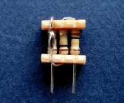
If you are interested in small footprint, high voltage and decent power dissipation and a package used in commercial electrostatic amplifiers, what about MELF package resistors?
Here a comparison of devices in Spice.
(I know it is not 100% reality.)
Seems that low capacitance is not everything.
Transconductance also counts in a circuit with global NFB.
Patrick
.
the diff pair, diff drive, ouput may do much better - even harmonics should cancel to the dergee that devices match
and you may get a SuSy benefit if you drive diff, measure the differential output distortion
Yes I do use MELF a lot, but I also like Susumu thin films, when dissipation is not an issue.
Patrick
Patrick
Hi,
Patrick, did You notice the FQD2N100/FQU 2N100?
Less Id, higher gfs, slightly lower capacitances.
Spice model is also available.
jauu
Calvin
Patrick, did You notice the FQD2N100/FQU 2N100?
Less Id, higher gfs, slightly lower capacitances.
Spice model is also available.
jauu
Calvin
Thanks Calvin.
I'll take a close look later.
(PS not as easy to mount as TO220, and leaded version seems not easily available). 😉
Patrick
I'll take a close look later.
(PS not as easy to mount as TO220, and leaded version seems not easily available). 😉
Patrick
Last edited:
Checked out in Spice.
Practically no difference (a few % at most) in distortion spectrum and bandwidth.
Also almost same price. Only temperature rise doubles.
🙂
Patrick
Practically no difference (a few % at most) in distortion spectrum and bandwidth.
Also almost same price. Only temperature rise doubles.
🙂
Patrick
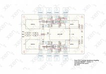
For those who wish to try out the circuit (with whichever MOSFET), a proposed P2P layout.
Black is component on top side of Vero Board.
Light blue is component on back side.
Dark green is normal wiring (silver plated copper).
Magenta is insulated jumper.
For the input / output coupling caps, you may use any MKP like WIMA MKP-4 or MKP-10.
The input caps want to be 4.7µF minimum, and any voltage above 63V.
The output caps should be 1µF 630V minimum.
Both should have 27.5mm lead pitch if using WIMA MKP10.
Shown here are Mundorf MCap footprints.
Patrick
.
Attachments
Last edited:
In a parallel discussion here :
http://www.diyaudio.com/forums/planars-exotics/248210-hv-transconductance-amp-idea.html#post3763764
I mentioned that the STAT concept is in essence also transconductance.
One can increase degeneration and add an Riv and an output buffer to make it zero global feedback.
Well, I could not resist the temptation.
It can be done without too much difficulties, and distortion though higher as expected is still very decent. (<-80dB at 1kHz).
And if this FET becomes available eventually :
http://www.diyaudio.com/forums/planars-exotics/248210-hv-transconductance-amp-idea.html#post3763765
http://www.onsemi.com/pub_link/Collateral/ENA2236-D.PDF
then a simple follower buffer should not be too difficult at all.
Or one could use the ixtp01n100 suggested in post# 13.
Patrick
What output levels do you plan on verifying distortion with your prototype build and how will you have to adapt your measurement infrastructure?
STAX uses 100Vrms differential output as bench mark for its commercial amplifiers.
So that is a good one to use.
Measuring is then really very easy.
You build a potential divider using FKP caps of sufficient voltage rating to make up 150p loading to the amp. (Dummy STAX so to speak.)
Then tap the middle 5 or 10%.
Any sound card or oscilloscope or distortion analyser can cope with that.
And of course you can philosophise what distortion a FKP cap has at 1kHz. 🙂
Patrick
I have requested a Spice model for the high voltage, low capacitance MOSFET from Onsemi that I found and disclosed at:
http://www.diyaudio.com/forums/planars-exotics/248210-hv-transconductance-amp-idea.html#post3763765
http://www.onsemi.com/pub_link/Collateral/ENA2236-D.PDF
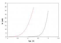
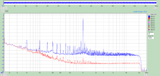
Again, if you believe in simulations, the low capacitances of the device cannot offset its low transconductance in the Pass STAT circuit.
Distortion is about 2x that of the Fairchild proposed above, and bandwidth almost halved.
For some other applications though, such as open loop followers, it can still be very useful.
Patrick
http://www.diyaudio.com/forums/planars-exotics/248210-hv-transconductance-amp-idea.html#post3763765
http://www.onsemi.com/pub_link/Collateral/ENA2236-D.PDF
Again, if you believe in simulations, the low capacitances of the device cannot offset its low transconductance in the Pass STAT circuit.
Distortion is about 2x that of the Fairchild proposed above, and bandwidth almost halved.
For some other applications though, such as open loop followers, it can still be very useful.
Patrick

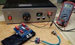
It has taken 9 years and a complete revised design to get to a working prototype. 🙂
This is just the first shot with no proper HV regulated supply, etc.
But it is alive and kicking.
We'll start a new thread once we have done all the optimisation and are happy with the final results.
Patrick
This is just the first shot with no proper HV regulated supply, etc.
But it is alive and kicking.
We'll start a new thread once we have done all the optimisation and are happy with the final results.
Patrick
Attachments
Wow, 2 likes in 20minutes !!
Didn't know there are interests in this exotic thing. 🙂
As you can see, not a lot of changes in the schematics.
But the devil is in the details.

Patrick
Didn't know there are interests in this exotic thing. 🙂
As you can see, not a lot of changes in the schematics.
But the devil is in the details.
Patrick
Last edited:
And right at the bottom of this Tubecad Blog, you can see a single-ended version explained.
https://www.tubecad.com/2009/09/blog0172.htm
Patrick
https://www.tubecad.com/2009/09/blog0172.htm
Patrick
Dear Patrick, I am always inspiration your design concept specially easily available parts with reasonable cost , Specially your 2SK209 recommendation & UDNeSS Revisions & much more schematic design.Wow, 2 likes in 20minutes !!
Didn't know there are interests in this exotic thing. 🙂
Patrick
Thanks
- Home
- Amplifiers
- Pass Labs
- Pass STAT Headphone Amplifier Concept