This is our interpretation of Nelson's original concept first published in 2010 :
http://www.diyaudio.com/forums/pass-labs/153030-semisouth-jfets-what-they-good-3.html#post2178227
Such a simply but nice concept, that it seems a waste not to make some use of it. 🙂
As an exception, we have included the Spice file so that you can play with different parameters.
Happy New Year,
Patrick
.
Attachments
Last edited:
Patrick I would look at the voltage divider on the mosfets, make that lower impedance. High impedance make it susceptible to deviations on transients.
Jan
Jan
How low, factor of 5 ?
That will also increase dissipation and cap size (not that it is an issue).
Patrick
That will also increase dissipation and cap size (not that it is an issue).
Patrick
Just changed as you suggested (5M->1M, 500k->100k, 10µ->47µ, etc.) and checked frequency response in Spice.
No apparent benefit. Frequency response remains identical.
So the limits were set somewhere else (feedback network fro upper limit and mu-follower bootstrap cap for lower limit).
The FET has really very low capacitance.
I think no change for now. 🙂
Patrick
No apparent benefit. Frequency response remains identical.
So the limits were set somewhere else (feedback network fro upper limit and mu-follower bootstrap cap for lower limit).
The FET has really very low capacitance.
I think no change for now. 🙂
Patrick
This is a Very interesting Thread !!!
I have been contemplating such a design for quite sometime.
I have finally gotten some HV fet's to work with.
I have some IRFBG30's and an assortment of various ones of 900v, 950v and 1200v Fets from ST as well.
I do have a 900v powersupply from an old Heathkit HW-101 that I may use, But I am thinking about a simple switching supply as well due to safety and the cost of filter cap reasons when I start venturing above 900v.
I will be watching for further development of this project!!!
Cheers !!
jer 🙂
IRFBG30 seems to have quite a bit higher capacitances. Transconductance also somewhat lower.
I think both bandwidth and distortion would suffer.
But of course you can try it out first in Spice and compare. 🙂
Patrick
I think both bandwidth and distortion would suffer.
But of course you can try it out first in Spice and compare. 🙂
Patrick
In my Previous Sims in Circuitmaker2000 it seemed to work pretty good but then I was also using and Opamp to drive them.
I haven't explored the same circuit it LTspice yet.
It is some times hard to find FET's with high voltage ratings with low capacitances.
Here is the list of ST devices I have,
STW4N150 1500V Nfet,
http://www.st.com/web/en/resource/technical/document/datasheet/CD00050744.pdf
STF6N95K 950V Nfet,
http://www.st.com/web/en/resource/technical/document/datasheet/CD00261184.pdf
STP21N90K5 900v Nfet,
http://www.st.com/web/en/resource/technical/document/datasheet/CD00255284.pdf
And some HV NPN BJT's BUL128D-B,
http://www.st.com/st-web-ui/static/active/en/resource/technical/document/datasheet/CD00001675.pdf
The 950V Nfet has the least amount of Capacitance value of the lot at only 450pf input and 30pf output values.
The 1500v Nfet is not too bad but it is up there, But acceptable at 1300pf in and 120pf out.
It is much less than many others I have found in this voltage range.
Here is the datasheet to the IRFBG30's I have,
http://www.vishay.com/docs/91124/91124.pdf
I have posted the schematics of my previous sim's earlier in another thread and one working model using IRF510's/740's/840's and such at 200v.
But again, I was using an opamp to drive the stacked FET and I was using a Power resistor for the top CS too.
It worked very good I just haven't had the time to get back into it since then (2008).
jer 🙂
Last edited:
I'm quite interested. I'm running tubes now, but I've always wondered what could be done on the solid state side.
http://www.fairchildsemi.com/ds/FQ/FQP3N80C.pdf
Crss 5.5p
Coss 54p
Ciss 543p
Yfs 3S at 1.5A
Not easy to beat. 🙂
Patrick
Crss 5.5p
Coss 54p
Ciss 543p
Yfs 3S at 1.5A
Not easy to beat. 🙂
Patrick
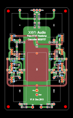
PCB first draft.
Since the active devices are so low cost, one can afford to spend on the passives.
Resistors are e.g. Caddock MK132 & Susumu 0805 thin film.
MK132 is rated at 400V 0.75W, compared to most axials like RN55 which are ~200V 0.25W.
And they take less footprint as a bonus.
😉
Patrick
.
Since the active devices are so low cost, one can afford to spend on the passives.
Resistors are e.g. Caddock MK132 & Susumu 0805 thin film.
MK132 is rated at 400V 0.75W, compared to most axials like RN55 which are ~200V 0.25W.
And they take less footprint as a bonus.
😉
Patrick
.
Attachments
Just changed as you suggested (5M->1M, 500k->100k, 10µ->47µ, etc.) and checked frequency response in Spice.
No apparent benefit. Frequency response remains identical.
So the limits were set somewhere else (feedback network fro upper limit and mu-follower bootstrap cap for lower limit).
The FET has really very low capacitance.
I think no change for now. 🙂
Patrick
Yes these things often show no effect in Spice. You may be OK with the original values - it's a kind of knee-jerk reaction from me if I see these high values with devices with dynamically changing capacitances.
Just keep it in mind when you see funny behaviour after you build it 😉
It's an interesting circuit indeed.
Jan
I made a few changes including lowering those values as you suggested, as well as changing the CCS to a single resistor.
The latter reduces 2nd harmonics quite significantly (single ended), though in balanced mode this has less effect.
The reduction of those high resistance values are two folds.
a) they are not easy to get;
b) lower values will reduce any effects of any possible MOSFET gate leakage.
🙂
Patrick
The latter reduces 2nd harmonics quite significantly (single ended), though in balanced mode this has less effect.
The reduction of those high resistance values are two folds.
a) they are not easy to get;
b) lower values will reduce any effects of any possible MOSFET gate leakage.
🙂
Patrick
Ixys ixtp01n100 with lower parasitic C, is better sized for ES headphones which really only need ~10 mA/side and is depletion mode which simplifies bias of the pull up
and Papa uses the more correct form of cascode sometimes called hawksford/baxandall although the history is even deeper - http://www.diyaudio.com/forums/solid-state/166306-origins-baxandall-super-pair.html
but a side consequence of the better performance, higher Q, is a greater tendency to oscillate at RF - more elaborate Zobel/damping may be needed
Last edited:
Yes, I was looking at those Fairchild devices.
Sadly I am stuck with what I can get as samples for the moment.
FWIW, lowering the values of the resistors only causes for a higher power rating for them.
As long as there is enough current flowing to charge the Gate capacitance for your applied frequency, that is all that is needed.
If you are trying to produce a square wave then as much as 5 times more current is needed as per my earlier sim's is acceptable (hence 5 times the bandwidth).
Raising their resistance may hender the HF performance.
This is also effective when driving the ESL as well.
Because of this I try to design for at least a 100Khz bandwidth even though I can't hear this high.
jer 🙂
> Ixys ixtp01n100 with lower parasitic C .....
Nice FET indeed.
But 4x the price, and 4x higher thermal resistance ?
I think I'll stick to Fairchild for now.
I am not exactly short of bandwidth, and I'd like to have more current driving capability.
10mA is fine for 20kHz, but current consumption goes up with frequency, so does distortion.
Patrick
with the 3 amp fairchild running ~ 1% of its rating you are spending as much or more current driving Q Cds than the C of popular ES headphones
cascode doesn't change that - only shifts which Q
much better to use the smaller die, lower parasitic C part, heatsink it well
if you look at ES project amp designs like Gilmore's Blue Hawaii, KGSS, KGSSHV, even the Stax T2 recreation - they all use <= 10 mA per side with SE, unmodulated ccs
I quite agree that >100 kHz small signal BW is good - but settling for just a little greater than 20 kHz power bandwidth/full amplitude slew limit really isn't a practical problem for real audio
after all vinyl playback, even with $k mc carts doesn't exceed 5 kHz power bandwidth/full amplitude slew limit - masters can't be cut hotter, styli can't track higher
Last edited:
2 Q in series cascade/totem pole - splitting the V equally is probably a better approach than cascode
the effective Q parasitic C is then nearly halved
AC balance requires a small C on one leg of bias divider to compensate for Crss
you can also use the reduced C cascade composite Q to cascode a low V part with desired characteristics (JFET?) for the "srpp derived" modulated pull up and the diff pair
Last edited:
> Ixys ixtp01n100 with lower parasitic C .....
Nice FET indeed.
But 4x the price
Says the person using Caddocks in the build 🙂
I get them at different prices. 😉
And you can replace a Caddock by 3x Dale RN55 for the same PCB foot print.
Will give you then about same voltage and dissipation rating.
Patrick
And you can replace a Caddock by 3x Dale RN55 for the same PCB foot print.
Will give you then about same voltage and dissipation rating.
Patrick
Last edited:
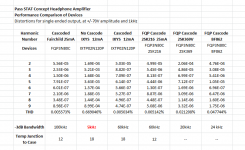
Here a comparison of devices in Spice.
(I know it is not 100% reality.)
Seems that low capacitance is not everything.
Transconductance also counts in a circuit with global NFB.
Patrick
.
(I know it is not 100% reality.)
Seems that low capacitance is not everything.
Transconductance also counts in a circuit with global NFB.
Patrick
.
Attachments
Last edited:
- Home
- Amplifiers
- Pass Labs
- Pass STAT Headphone Amplifier Concept