yes, of course, but that way there is no trouble and there is no 20 posts ....... 
so, just to conclude Paolo's stance - use breadboard only when small currents are involved; and even then check trice quality of all connections
so, just to conclude Paolo's stance - use breadboard only when small currents are involved; and even then check trice quality of all connections


It was a problem with one of the shitty breadboard jumpers. If I would have reused that jumper I would have looked pretty stupid too! Thanks for trying to help. I live by my breadboard and will probably die by it (or get tomatoed by diyaudio members) 🙉I suggested no board in my first post. 🙂
Hi,
I am also in the process of matching the output MOSFETs (IRFP240) using the same procedure from Nelson released in ’93. In one other threat about device matching (I can’t find it anymore), one recommends that the devices should be matched using current values as close as possible to those they will be facing when later operating in the amplifier. Also, it was mentioned that the temperature should also be about the same as their future environment…
Now I have some doubts on how to proceed. Shall I match them “cold” with the 50-56 Ohm resistors as specified in Nelson’s doc, or shall I run much higher currents through it to make the MOSFETs rise to 50-60°C? That would require several amps, so the resistor between the power supply and the drain should be less than an Ohm…
I’d be thankful for advices on how to proceed!
Cheers,
Denis
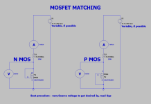
No need to emulate lab conditions for output device matching (real world temps are nice but not critical). Voltage is also not critical.
Ensure, as you say, similar current conditions as the real circuit will have, and use a timer so that you read the Ugs after, for example, ten seconds after turn-on on all devices during matching, and or when the Ugs settles (which coincidentally takes about ten seconds). This means you need to do some math to find resistor vs voltage values that will provide the correct current.
Ensure a rest of the sink between devices so that temps are approximately the same, alternatively use two different sink locations.
Approximately equal torque also helps but I never did find that to be a real world relevant issue.
For example, for 0A5 (500mA) per device, and using a 50R resistor, set your PSU to 29 volts and you are there. For 0A25, set it to 16,5. close enough.
Last edited:
thanks for your reply. So basically, I should use the same Vcc than the actual power supply rails in the amplifier, and same output resistors (6x 0.47 Ohm in parallel)?
No, sorry, that is not what I meant.
Focus on current, not voltage, and use a heatsink during matching:
I meant to use the values (in this case 50 ohm resistor vs 16V5/29V) that provide the correct current that the MOSFET will be biased to in the real circuit. To rule out factors such as draft, and to reduce risk of blowing the devices up during matching, I always attach the MOSFETs to a heatsink during matching.
My suggestions are as described above, but you can decrease resistor values to accomodate lower voltage during testing. I think I used 25R.
Make sure you use a big high wattage resistor.
In any case you cannot measure Ugs simply by recreating the original circuit, much easier to follow Pa’s schem.
Also, if this is an F4 or BA-3 the 6 source resistors are not in parallel, but that is not relevant for matching anyways.
Oh ok, thanks for the clarification. it is for a A2 which I have for quite a while and that I want to finish now. They require 2x 6 N-Ch Mos for each Channel. And indeed, I read the schematics too quickly, the resistors in the circuit are 6x 1 Ohm, and not parallel (each R is between the MOS's source pin). The 6x0.47 Ohm in parallel are attached to the drain. But as you say, none of them are relevant here.
Yes I already prepared a heatsink for that purpose, with silicon pad. Yesterday I gave it a quick try and had quite low current values (around 180mA) despite 6.2 Ohm Resistor (50W R array, also mounted on a separate heatsink). I'll have to check again, I suspect a PEBDAC (Problem Exists Between Device And Chair)...
I'll report tonight.
ps: remember to include what voltages you are using. If you do not have an adjustable lab supply, please include the fixed rail voltage you are using. Then potential adjustments will have to happen @ the resistor and nowhere else 🙂
no worries, I have a proper lab supply. Here you can see the resistors mounted on a heatsink and the MOSFET on its own heatsink:

I see! Nice setup!! Well prepared 🙂 with such low resistance you should achieve 350mA with approx 8V5 on the supply. Given using one of the resistors (I see you have three).
well yesterday I was far away from that... approx 180mA with 15.00Vcc...so something is wrong for sure. Maybe I had 1 or 2 beers too much... I'll check everything tonight and will keep you posted.
Just reduce the voltage 🙂
But I am unsure whether your circuit is correct. There should be no need to measure current. It is given in the V/R ratio.
But I am unsure whether your circuit is correct. There should be no need to measure current. It is given in the V/R ratio.
Last edited:
Have another look at this article by NP:
https://www.passdiy.com/project/articles/matching-devices
Based on this I use 170mA just like Pa for IRFP240's. 1000's are happily running in Pass/FW clones, Ampeg Bass amps, Llano rebuilds, etc.
Post 16 has the details
https://www.diyaudio.com/community/...ut-the-pass-mosfet-matching-technique.398291/
Yes that's the point, I was wondering because another threat mentioned that the mosfets should be tested at operating temp, and with 170mA bias they stay completely cold, hence the confusion.Based on this I use 170mA just like Pa for IRFP240's.
Do your mosfets get warm when running at 170mA?
They don't get warm, and I run them for ~10 sec. So no heatsinks. You'll see the Vgs settle by 10 seconds. I mark the Vgs reading on the MOSFET with a fine tip sharpie and set them aside. Sort the batch by VGS when you've measured them and group them together.
I make sure they are all temperature stable for the matching session. Translation: if they are delivered on a cold winter day or hot summer day, I let them set inside in my temperature-controlled home for a day or so before I begin matching. Simple.
I make sure they are all temperature stable for the matching session. Translation: if they are delivered on a cold winter day or hot summer day, I let them set inside in my temperature-controlled home for a day or so before I begin matching. Simple.
OK, done it again (sober - so this is ruled out as a possible cause) but I still get different values from those expected. R = 46,8 Ohm
Vcc voltage is 15V, and the circuit draws 0,136A only

Vgs = 8,63V. I tested with another multimeter, with similar results +/-0,1V)

Here's my setup. Do you anything wrong?

all green wires are ground.
Red coming from the PSU is +15V, runs through R1 (47 Ohm, measured), and from there to pins 1(Gate - black) and 2 (Drain - red). Source pin is the green wire on the right that goes to ground.
and seen from the top, left to right we should have gate, drain, source.
and yeah, I get all my components from mouser, so these are genuine parts, no doubt there.
Vcc voltage is 15V, and the circuit draws 0,136A only
Vgs = 8,63V. I tested with another multimeter, with similar results +/-0,1V)
Here's my setup. Do you anything wrong?
all green wires are ground.
Red coming from the PSU is +15V, runs through R1 (47 Ohm, measured), and from there to pins 1(Gate - black) and 2 (Drain - red). Source pin is the green wire on the right that goes to ground.
and seen from the top, left to right we should have gate, drain, source.
and yeah, I get all my components from mouser, so these are genuine parts, no doubt there.
- Home
- Amplifiers
- Pass Labs
- Pass Mosfet Matching Help