Feel like speculating in aluminum futures?
There are pictures and some basic specifications of the XA200 on the Pass Labs site.
No, I haven't built the Aleph-X prototype yet--hope to start on that this weekend or perhaps next week. My fingers are crossed that nothing goes wrong in the meantime to eat up my free time. Don't need no more computer viruses 'round here...
Grey
Grey,
Please post your results as you work on this....
I am going to be trying the same thing within a couple of months except with more outputs than the Aleph...
I would be very interested in knowing about the hurdles...
Thanks,
Steve
Please post your results as you work on this....
I am going to be trying the same thing within a couple of months except with more outputs than the Aleph...
I would be very interested in knowing about the hurdles...
Thanks,
Steve
Well, the easiest part for me to guess is the supply, which would need to be about +/-35VDC at 8.5A idle.
As for the actual gain circuit, my best guess fow now is that it's basically two standard Aleph channels bridged together at their inverting inputs. I've tried this in simulations and it seems to work, although I can't tell whether to simply ground both of the noninverting inputs or tie them together and float them off ground by 10K ohms or so.
In the model, floating this junction gives increased second order distortion when measuring one side of the load to ground (third order distortion is not much affected), as compared to grounding it. Of course, you really need to measure these effects *across* the load, but I've yet to figure out how to do that in the simulator.
Maybe I'll just have to make a real one. 🙂
Rethinking the above post, it seems that my terms may have been incorrect, or at least confusing. What I mean to say is that the two channels are bridged together AND DRIVEN via their inverting inputs, using a balanced input signal.
What actually ties the two channels together in this scenario is the interconnection of their two NONinverting inputs. Thinking more about this, I believe that this point must be allowed to float for true s-s operation to occur. Of course, I'd be interested in any light that NP is willing to shed on this!
What actually ties the two channels together in this scenario is the interconnection of their two NONinverting inputs. Thinking more about this, I believe that this point must be allowed to float for true s-s operation to occur. Of course, I'd be interested in any light that NP is willing to shed on this!
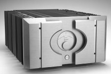
Don't forget this picture. I love the finished appearance.
An externally hosted image should be here but it was not working when we last tested it.
I'm not so sure about this value!Well, the easiest part for me to guess is the supply, which would need to be about +/-35VDC at 8.5A idle
Not sure about this either. Nelson hinted that one of the major "hurdles" in running the X-Front into a SE back was the DC offset, which sort-of implies to my simple non-EE mind that he isn't running the Aleph backs in a balanced mirror arrangement.two channels are bridged together AND DRIVEN via their inverting inputs, using a balanced
What say some of the clever folks?
(excluding NP, as I don't think he should be expected to answer this thread ..... unless he feels inclined 🙂 )
cheers, mark
mark,
For a 200W/8 ohm amplifier you need a +/- 57V peak output swing, which in a bridge design means just over 28V from each side of the output stage. This implies at least +/- 29V rail voltage; I spec'd it at 35V to allow some margin and because it's about what you'd get from a standard 2X25V transformer. Also, 2 x 35V x 8.5A = about 600W dissipation, which is the rating for the X1000 chassis. Also note that 8.5A is "more than double" the idle current used in the X1000, so at least in this regard it more or less matches the description given on the Pass Labs site.
As for the topology, I admit that I don't know exactly what NP is doing, but I do believe that bridging two Aleph channels together would take care of the DC offset problem. However, I must also apologize for again having inadvertently given an incomplete description of the setup. What I said (the second time) above is, I believe, correct as far as it goes, but there is just a bit more to it. I may post more details later if I get permission. 🙂
Its gynormous
If you are going to try this out, you're going to need a huge case like the commercial version. At 600W idle, its going to be like a large tube amp for heat production. This is not an undertaking for the faint at heart, and it will be expensive to build, especially for a single pair of amps.
Having said all that, I wish you a lot of luck, I'd like to see you succeed spectacularly.
not too beaucoup
Big as it is, the XA isn't any larger relative to its power output than the Alephs. So, for example, you could build a 100W XA on the same chassis as an Aleph 2, if you wanted to.
Big as it is, the XA isn't any larger relative to its power output than the Alephs. So, for example, you could build a 100W XA on the same chassis as an Aleph 2, if you wanted to.
On the power output of XA relative to Aleph, understood and agreed that the thermal constraints are the same. So with that in mind - two things:
First, the XA-600 is going to have to be large, that was my only point. It's either large, or it has fans. My Aleph is hotter I think than what Nelson can allow his commercial offerings to be. He has to answer to customers; I dont.
Second, I'm thinking that one day I may replace the Aleph 2 that's in that chassis with an "XA-100". All I'd have to do is new boards and perhaps drill and tap again into the heatsinks. Oh ya I can hear it now !!!!!
WayneS,
If the XA is a bridge design like the other X series amps (and whether or not it's a bridged pair of Aleph channels), you'd also need about half the power supply voltage at double the current to complete the conversion. The effort still might be worthwhile, and certainly manageable for someone who's already built his own Aleph 2s.
If the XA is a bridge design like the other X series amps (and whether or not it's a bridged pair of Aleph channels), you'd also need about half the power supply voltage at double the current to complete the conversion. The effort still might be worthwhile, and certainly manageable for someone who's already built his own Aleph 2s.
Hi Nelson,
In another thread I commented on the look of the new XA-200. It's a beautiful piece of work. That front faceplate obviously took some vision to figure out and looks to be quite complex to machine. Maybe some day I'll get that creative.... for now, a bunch of flat panels bolted to some heatsinks is gonna have to do.
For now I'm enjoying my Aleph 2s enormously. Changing to an XA would mean taking them out of service for a while. Maybe I'll just go all-out and do an XA-200 or so one day. I still have a huge smile on my face whenever I fire them up....
The credit for the metal goes to Desmond Harrington.
You've seen his work before; we stole him from Krell
some years ago. 🙂
You've seen his work before; we stole him from Krell
some years ago. 🙂
- Status
- Not open for further replies.
- Home
- Amplifiers
- Pass Labs
- Pass Labs XA200 amplifier