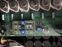
The right heatsinks of my X250 are much cooler than the left heatsinks. The front meter's position at around 11AM. Can some one advise me how to check/adjust bias and offset? Photo inside my X250 below. Many thanks 🙂
An externally hosted image should be here but it was not working when we last tested it.
here are your pictures , properly shrinked
will reply tonight with specifics
will reply tonight with specifics
Attachments
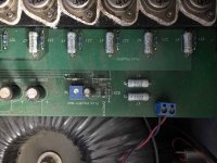
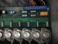
Looking at those photo's that ZM has posted the amp internals could do with a good careful clean as well.
make list - from top to bottom (when amp face is looking at your belly) , all source resistors , voltage across them (each one)
list for left side , list for right side
list for left side , list for right side
.06 Volts across each .47 Ohm resistor. Slow and careful you don't want to blow the output transistors they are rare.
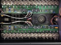
Nice to see those internals. That one almost looks build-able.....
If only one had the schematics. 😀
If only one had the schematics. 😀
I just looked up this circuit which looks really cool. I don’t want to hijack this thread but if someone is willing to PM me, can one explain for a rookie how this Supersymmetry circuit works? I did some searches and one promising thread got derailed real fast and went no where. One article I read makes it look like it’s Class A push pull in the 1st stage and Class AB in the output?
http://www.firstwatt.com/pdf/art_susy.pdf
Should do the trick for you
X100 backengineered here
Might be a good one for you too
Should do the trick for you
X100 backengineered here
Might be a good one for you too
http://www.firstwatt.com/pdf/art_susy.pdf
Should do the trick for you
X100 backengineered here
Might be a good one for you too
AH! “SUSY” went over my head! Thank you!
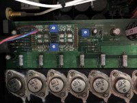
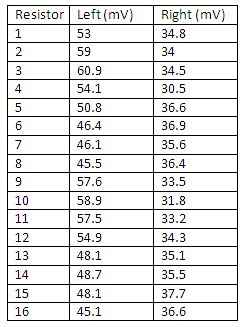
I measured voltage across the 0.47 ohm resistors (16 along the left and another 16 along the right which are highlighted in red rectangle in the photo below). I found that the voltage increased over time since I powered on the X250 but at any moment, the voltage across the 0.47 ohm resisters along the right is lower that of the ones along the right. Below is the results that I measured at 50 minutes after turn on the X250 (not connect to neither rca/xlr inputs nor speaker).
From top to bottom (the amp face is looking at my belly).
Left (mV)
1. 53
2. 59
3. 60.9
4. 54.1
5. 50.8
6. 46.4
7. 46.1
8. 45.5
9. 57.6
10. 58.9
11. 57.5
12. 54.9
13. 48.1
14. 48.7
15. 48.1
16. 45.1
Right (mV)
1. 34.8
2. 34
3. 34.5
4. 30.5
5. 36.6
6. 36.9
7. 35.6
8. 36.4
9. 33.5
10. 31.8
11. 33.2
12. 34.3
13. 35.1
14. 35.5
15. 37.7
16. 36.6
I would start cleaning all internal before I would power up the amp. It looks very dirty. The dirt could have some influence on the electrical performance. The question is what to use? …..isopropyl alcohol?
soft wide brush combined with compressed air to remove dirt
for electronics , I'm finding handy old vacuum cleaner which is having same size hole (for hose) on both sides , with hose connected on output side - lesser pressure than air compressor
gently clean dust with brush and remove it with air
take allen key and check how tight are all allen bolts
after that - take two pairs of crocodile clips and two DVMs , set to 200mV
one pair of crocs - across one source resistor nearest to front of amp (belly side ) , second pair of crocs across source resistor on back side of amp
connect crocs to DVMs , placed near the amp
put lid on , power amp on and wait for temp and readout equilibrium
after that - pull lid off , fiddle with minus polarity bias trimpot , then with plus polarity bias ; take care to do it gently, in smaaaaaaaaaal attempts , making just half-way steps to desired value , putting lid on again to let it settle
make pauses of at least 10mins between hops
so , in few hops , you'll get from average 35mV to average 60mV
you can correct other channel too , to be slightly more biased than is it now
when done ,just in case - re-check output offset , both between outputs and between outputs and GND
general procedure and tips : Pass Labs X150.5 , checking/adjusting offsets ,Iq and gain | Zen Mod Blog
for electronics , I'm finding handy old vacuum cleaner which is having same size hole (for hose) on both sides , with hose connected on output side - lesser pressure than air compressor
gently clean dust with brush and remove it with air
take allen key and check how tight are all allen bolts
after that - take two pairs of crocodile clips and two DVMs , set to 200mV
one pair of crocs - across one source resistor nearest to front of amp (belly side
) , second pair of crocs across source resistor on back side of ampconnect crocs to DVMs , placed near the amp
put lid on , power amp on and wait for temp and readout equilibrium
after that - pull lid off , fiddle with minus polarity bias trimpot , then with plus polarity bias ; take care to do it gently, in smaaaaaaaaaal attempts , making just half-way steps to desired value , putting lid on again to let it settle
make pauses of at least 10mins between hops
so , in few hops , you'll get from average 35mV to average 60mV
you can correct other channel too , to be slightly more biased than is it now
when done ,just in case - re-check output offset , both between outputs and between outputs and GND
general procedure and tips : Pass Labs X150.5 , checking/adjusting offsets ,Iq and gain | Zen Mod Blog
general procedure and tips : Pass Labs X150.5 , checking/adjusting offsets ,Iq and gain | Zen Mod Blog
Yay. My x150.5 is famous with its own web page 😀


Thank you very much, I followed your instruction and it worked well 🙂
soft wide brush combined with compressed air to remove dirt
for electronics , I'm finding handy old vacuum cleaner which is having same size hole (for hose) on both sides , with hose connected on output side - lesser pressure than air compressor
gently clean dust with brush and remove it with air
take allen key and check how tight are all allen bolts
after that - take two pairs of crocodile clips and two DVMs , set to 200mV
one pair of crocs - across one source resistor nearest to front of amp (belly side
connect crocs to DVMs , placed near the amp
put lid on , power amp on and wait for temp and readout equilibrium
after that - pull lid off , fiddle with minus polarity bias trimpot , then with plus polarity bias ; take care to do it gently, in smaaaaaaaaaal attempts , making just half-way steps to desired value , putting lid on again to let it settle
make pauses of at least 10mins between hops
so , in few hops , you'll get from average 35mV to average 60mV
you can correct other channel too , to be slightly more biased than is it now
when done ,just in case - re-check output offset , both between outputs and between outputs and GND
general procedure and tips : Pass Labs X150.5 , checking/adjusting offsets ,Iq and gain | Zen Mod Blog
It's been a while and I checked DC voltage between positive and negative outputs, one channel shows 22mV and other channel shows 46mV. I read in a post that it should be less than 10mV. Can someone teach me how to adjust Differential offset? Thank you very much!
- Home
- Amplifiers
- Pass Labs
- Pass labs X250 - how to adjust/check bias, offset