Hello;
I have an older X150, it has board # XA02MB2, S/N: 09404. I bought it used a few months ago, and listened to it for several weekends. I noticed that it was making a thump in my speakers at turn off, and later noticed it also made noise to a lesser degree at turn on. I was using single ended RCA, and had the XLR shorting pins in the correct holes, 1 and 3.
I decided to take a look inside, when I did I discovered that all the top cover screws were loose, so I have to think the previous owner was in there for some reason. I was planing on putting in a suppression capacitor to stop the power surge to the speakers. After searching and reading I discovered that Pass Labs does not use any suppression capacitors in their design.
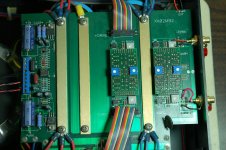
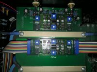
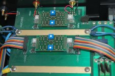
There are 2 ribbon cables connected to the board next to the bias pins. The right side is turned around and plugged in backwards. This is what concerns me at the moment. The amp appears to work as it should (besides the thump). I am including several pictures. I have seen pictures of X150 amps with the XA02MB5 board and the ribbon cable is not turned around like mine.
Can anyone verify that this is the correct position for the cable on the right side?
Thank You!
I have an older X150, it has board # XA02MB2, S/N: 09404. I bought it used a few months ago, and listened to it for several weekends. I noticed that it was making a thump in my speakers at turn off, and later noticed it also made noise to a lesser degree at turn on. I was using single ended RCA, and had the XLR shorting pins in the correct holes, 1 and 3.
I decided to take a look inside, when I did I discovered that all the top cover screws were loose, so I have to think the previous owner was in there for some reason. I was planing on putting in a suppression capacitor to stop the power surge to the speakers. After searching and reading I discovered that Pass Labs does not use any suppression capacitors in their design.
There are 2 ribbon cables connected to the board next to the bias pins. The right side is turned around and plugged in backwards. This is what concerns me at the moment. The amp appears to work as it should (besides the thump). I am including several pictures. I have seen pictures of X150 amps with the XA02MB5 board and the ribbon cable is not turned around like mine.
Can anyone verify that this is the correct position for the cable on the right side?
Thank You!
Attachments
I would suggest to contact Pass Lasb directly with your query. It's unlikely anyone here is familiar with all the different boards versions but the PL boys.
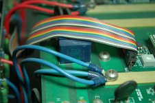
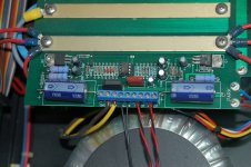
colors on cable are same on both sizes (which I can see from your pics) , same as arrangement of pins of both sides (which is a fact from SM)
right cable is just assembled in "wrong for an eye" way , but electrically is correct
thump is most likely there either because of amp out of settings for Iq and offsets , or dried caps
check absolute and relative offsets , both in cold and hot state and inform here
for more info , see x150 amp related post in my blog , even if is later model than yours, you'll see how to check offsets
Last edited:
And it is not possible to insert the ribbonconnector the wrong way. it has a senter slot on one side.
Audiosan, I remember doing it when I was younger..it was sometimes needed on old 8088 PC etc.
Depending on the stiffness of the plastic material of the socket you can force it in...
It would surpise me that it was done that way at PL though...
Depending on the stiffness of the plastic material of the socket you can force it in...
It would surpise me that it was done that way at PL though...
Papa was in a hurry while assembling the cable,had too much emails from Greedy Boyz,to reply to...
who can complain?

who can complain?
Still confused...
I did contact Pass labs, about the thump. Kent English emailed back and asked if the shorting pins were in the correct position, and I said yes, they were. He suggested bringing it in to be bench tested. I asked if schematics or service manuals were available, he said no.
I emailed a picture of the cable and asked if that was the correct way to be connected. I told him I was going to try to check and adjust the bias and offsets as directed here in Gelly's and Old & Crankys posts, and ZenMod's Blog about the X150.5. I never heard back. I don't know if he didn't receive the email, or if he has reason to not respond.
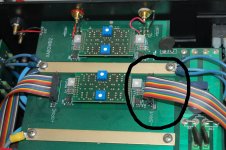
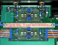
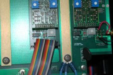
If you look at the photo's of the other X150 amps which have the XA02MB5 board, you will see that the colors on the ribbons are opposite each other on the right and left plugs connected to the board. Mine are the same, but only because the plug is turned around to plug in. The plug can be pushed down on the pins either way, the plug does not have anything to make only one position possible.
Because there is a difference in the position of the plugs and the way the colors match or oppose each other I am unsure of the position mine should be. It does work as it is, and I am not going to flip it around and turn it on to see what happens.
Zen Mod you said " (which is a fact from SM) ", does this mean you have seen a service manual for the X150 and mine is correct as is? I don't understand how a newer board for the same model would have the opposite position.
You can say I am confused.
I did contact Pass labs, about the thump. Kent English emailed back and asked if the shorting pins were in the correct position, and I said yes, they were. He suggested bringing it in to be bench tested. I asked if schematics or service manuals were available, he said no.
I emailed a picture of the cable and asked if that was the correct way to be connected. I told him I was going to try to check and adjust the bias and offsets as directed here in Gelly's and Old & Crankys posts, and ZenMod's Blog about the X150.5. I never heard back. I don't know if he didn't receive the email, or if he has reason to not respond.
If you look at the photo's of the other X150 amps which have the XA02MB5 board, you will see that the colors on the ribbons are opposite each other on the right and left plugs connected to the board. Mine are the same, but only because the plug is turned around to plug in. The plug can be pushed down on the pins either way, the plug does not have anything to make only one position possible.
Because there is a difference in the position of the plugs and the way the colors match or oppose each other I am unsure of the position mine should be. It does work as it is, and I am not going to flip it around and turn it on to see what happens.
Zen Mod you said " (which is a fact from SM) ", does this mean you have seen a service manual for the X150 and mine is correct as is? I don't understand how a newer board for the same model would have the opposite position.
You can say I am confused.
Attachments
I did not mean to make text larger or bold at end of previous post. I tried to edit it to normal text but was past the 30 minute time to do so.
The cable is okay. These were built for a time by Tibi electronics and shipped to us for test and burn in. Where are you located?
Chico, about 90 miles north of you if you are in Auburn. I have to get up at 4 a.m. and be at work at 6 a.m. so I won't be able to continue tonight. After Christmas I can give more information and respond to questions. I'm going to my Mom's, and she does not have internet access.
Thanks Wayne for the verification, I will get some readings this weekend when I'm back.
Thanks Wayne for the verification, I will get some readings this weekend when I'm back.
Testing,readings
I took some readings about 3 weeks ago, and again last weekend. Following ZenMod's X150.5 instructions,and from posts here on diyAudio. I first adjusted the bias. The first time I was reading the temperature as fahrenheit, adjusting to 25 to 30 above room temperature. So I did not get the desired temps, I realized later that all readings here were done in celsius. The room temp was 74 degrees or 23.3 celsius, adjusted over time to the following:
A left front bias 100 degrees or 37.7c, 115v
C right front bias 98 degrees or 36.6c, 114v
B left rear bias 99 degrees or 37.2c 118v
D right rear bias 100 degrees or 37.7c 118v
With the bias set as above, I then moved on to the differential offset ( the red + / black - speaker terminals) and then the absolute offset ( any speaker terminal and rca ground wire).
right side differential offset -.003 was -.017
left side absolute differential 06.8 was -4.23
left side differential offset 0.1 was .065
left side absolute differential -10.85 was 7.30
The absolute offsets will only adjust up or down a very small amount, they stay close to the same. I kept turned the right absolute pot all the way to the right and it changed from 4.20 to 4.28, I turned all the way to the left and it changed from 4.20 to 4.30. The left side from 7.30 to 7.64 turned all the way to the right, and up to 7.58 all the way to the left. At center position it would stay at 7.6.
So, the differential offset seems normal, but the absolute offset is out of whack and not cooperating.
I went back to the bias settings to check if any changes after doing the offsets. The left side was at 0.00v, It would not adjust up or down turning the pot. At this point, I thought it best to just turn the amp off.
The next weekend, I started again. I checked the bias, and differentials after turning on the amp, without allowing time to warm up to operating temperature.
A left front bias .001
C right front bias .034
B left rear bias .001
D right rear bias .133
right side differential offset .014
left side absolute differential 9.02
left side differential offset .002
left side absolute differential 11.55
The next day I reset the bias again: inside temp 21.1c 70 degrees
A left front bias 37.6c, .138v
C right front bias 38.0c, .138v
B left rear bias 37.6c, .136v
D right rear bias 38.0c, .138v
I checked the differentials.
As before, I could get the differential offsets close to zero, and they would stay close to this range, going up or down just a little.
The absolute offsets won't stay where I try and set them. The left goes up and down and won't settle. The right won't go lower than 3.9, and starts going up again.
I again checked the bias, and it was way off. The rear bias was at .157 both sides and was going up, it went up to .172 and .169 in a minute or two. The front bias was at .200 and .197, it went up to .205 and .200 in a minute. Time to turn off the amp again.
Earlier I did check the bias pins and they were all at 1.2 ohms.
I don't think any adjustments I make will bring this amp into spec. Initially it was the thump that concerned me, then the position of the multicolored wire that looked backward. Now I'm concerned about not being able to properly adjust the bias and differential and absolute offsets.
I understand something is wrong or not working as it should. No, I do not have the knowledge or skills to determine the cause of these symptoms.
https://www.diyaudio.com/forums/pass-labs/205030-pass-x150-sit-overall-line.html
Old'N'Cranky replaced some capacitors and got his back in spec. He didn't really state which ones he replaced. I was thinking of replacing all of the capacitors and then resetting again. I don't know if it will work, but worth a try. These should work and would be a start:
https://www.mouser.com/ProductDetail/Cornell-Dubilier-CDE/CGS313U050W4C?qs=sGAEpiMZZMtZ1n0r9vR22bNos12dWCDWkF3FQGHCpTA%3D
I believe my X150 is one of the earlier ones, 1999-2000? S/N:09404, and XA02MB2 board version, and the 2 boards referred to as USG4 are different and have no markings on them. It could be one of these boards is failing as determined in gelly's post: https://www.diyaudio.com/forums/pass-labs/343635-help-pass-x150-dc-output-differential-settings.html
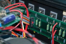
This amp is close to 20 years old, so I think the 4 power supply capacitors and the smaller 8 on the board should be replaced. At this point I think that should be my next step. If new capacitors don't cure it's current defective state, then I will take it to Pass Labs and ask them to diagnose it. Thank you for reading and any advice or instruction you may have.
I took some readings about 3 weeks ago, and again last weekend. Following ZenMod's X150.5 instructions,and from posts here on diyAudio. I first adjusted the bias. The first time I was reading the temperature as fahrenheit, adjusting to 25 to 30 above room temperature. So I did not get the desired temps, I realized later that all readings here were done in celsius. The room temp was 74 degrees or 23.3 celsius, adjusted over time to the following:
A left front bias 100 degrees or 37.7c, 115v
C right front bias 98 degrees or 36.6c, 114v
B left rear bias 99 degrees or 37.2c 118v
D right rear bias 100 degrees or 37.7c 118v
With the bias set as above, I then moved on to the differential offset ( the red + / black - speaker terminals) and then the absolute offset ( any speaker terminal and rca ground wire).
right side differential offset -.003 was -.017
left side absolute differential 06.8 was -4.23
left side differential offset 0.1 was .065
left side absolute differential -10.85 was 7.30
The absolute offsets will only adjust up or down a very small amount, they stay close to the same. I kept turned the right absolute pot all the way to the right and it changed from 4.20 to 4.28, I turned all the way to the left and it changed from 4.20 to 4.30. The left side from 7.30 to 7.64 turned all the way to the right, and up to 7.58 all the way to the left. At center position it would stay at 7.6.
So, the differential offset seems normal, but the absolute offset is out of whack and not cooperating.
I went back to the bias settings to check if any changes after doing the offsets. The left side was at 0.00v, It would not adjust up or down turning the pot. At this point, I thought it best to just turn the amp off.
The next weekend, I started again. I checked the bias, and differentials after turning on the amp, without allowing time to warm up to operating temperature.
A left front bias .001
C right front bias .034
B left rear bias .001
D right rear bias .133
right side differential offset .014
left side absolute differential 9.02
left side differential offset .002
left side absolute differential 11.55
The next day I reset the bias again: inside temp 21.1c 70 degrees
A left front bias 37.6c, .138v
C right front bias 38.0c, .138v
B left rear bias 37.6c, .136v
D right rear bias 38.0c, .138v
I checked the differentials.
As before, I could get the differential offsets close to zero, and they would stay close to this range, going up or down just a little.
The absolute offsets won't stay where I try and set them. The left goes up and down and won't settle. The right won't go lower than 3.9, and starts going up again.
I again checked the bias, and it was way off. The rear bias was at .157 both sides and was going up, it went up to .172 and .169 in a minute or two. The front bias was at .200 and .197, it went up to .205 and .200 in a minute. Time to turn off the amp again.
Earlier I did check the bias pins and they were all at 1.2 ohms.
I don't think any adjustments I make will bring this amp into spec. Initially it was the thump that concerned me, then the position of the multicolored wire that looked backward. Now I'm concerned about not being able to properly adjust the bias and differential and absolute offsets.
I understand something is wrong or not working as it should. No, I do not have the knowledge or skills to determine the cause of these symptoms.
https://www.diyaudio.com/forums/pass-labs/205030-pass-x150-sit-overall-line.html
Old'N'Cranky replaced some capacitors and got his back in spec. He didn't really state which ones he replaced. I was thinking of replacing all of the capacitors and then resetting again. I don't know if it will work, but worth a try. These should work and would be a start:
https://www.mouser.com/ProductDetail/Cornell-Dubilier-CDE/CGS313U050W4C?qs=sGAEpiMZZMtZ1n0r9vR22bNos12dWCDWkF3FQGHCpTA%3D
I believe my X150 is one of the earlier ones, 1999-2000? S/N:09404, and XA02MB2 board version, and the 2 boards referred to as USG4 are different and have no markings on them. It could be one of these boards is failing as determined in gelly's post: https://www.diyaudio.com/forums/pass-labs/343635-help-pass-x150-dc-output-differential-settings.html
This amp is close to 20 years old, so I think the 4 power supply capacitors and the smaller 8 on the board should be replaced. At this point I think that should be my next step. If new capacitors don't cure it's current defective state, then I will take it to Pass Labs and ask them to diagnose it. Thank you for reading and any advice or instruction you may have.
Attachments
in this particular case , just think how to solve 90 miles, after speaking with Wayne or other guys at PL ( I believe/hope PL Ladies are spared of that 🙂 )
that's pretty much best scenario
that's pretty much best scenario
We can take care of it for you. I suspect you need new UGS modules. Ship it, drive it and we will make it better than new.
Usg modules...
Hello; and thank you for your quick responses. I was thinking I should replaced all the capacitors before bringing it in to Pass Labs. Once they have it and determine what needs to be done,replace parts and make required adjustments, I would have an amp that should last another 20 years. I do plan on keeping it.
I don't want to have it returned repaired, and then have to replace capacitors and re adjust everything again at a later time.
Wayne, if you think it is best to bring it in as is and this would make it easier for diagnosis and repair, I can do that. It seems to make sense to replace all capacitors first, eliminating one preventive maintenance repair towards the amps recovery, and then bring it if for USG module replacement.
Let me know what you think.
Thank you...
I have not tested them, just thought they may be at the end of their lifespan at 15 to 20 years old. I am going to try and get a couple hours off work in a week or two and bring it in.
I have not tested them, just thought they may be at the end of their lifespan at 15 to 20 years old. I am going to try and get a couple hours off work in a week or two and bring it in.
Just get them to completely refurbish it. You’ll be glad in the long run.
It will be so much faster for them to do it.
- Home
- Amplifiers
- Pass Labs
- Pass Labs X150 ribbon cable position incorrect?