Does using soft start boards and having the soft start on the PSU (double soft start with thermisters) have any effect? Probably not? Just curious as I see soft start PCBs with snubbers being used before the rectifiers.
What's the output DC voltage?
Since you have dual PS, suggest to power ON and test one channel at a time.
Since you have dual PS, suggest to power ON and test one channel at a time.
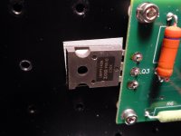
No voltage across 0.47 resistors.Yes completely dual mono I left the right channel pots off and turned P1 then P2 on the left channel up by small increments until with both fully cranked I still have no voltage across R7 or R6.I then turned both fully off and repeated the performance on the right channel with identical results.Not sure if soft start boards have an effect but voltage at the amplifier boards reads good throughout testing. I can unplug the rectifiers for 1 channel.The power supply voltage for both channels remains constant for every adjustment.I have made to date.I checked the Mosfets and Q3 is IRFP9140 and Q4 is IFRP140
Attachments

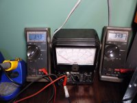
Output voltage at the speaker terminals has always been zero the Simpson is set at 2.5 volts fullscale and connected to the terminals of the channel being adjusted during P1 and P2 adjustments I have not noticed a flicker at either polarity DC or on the AC setting
In your pictures in post #4 319, both voltages are positive (can't see what you have the meters connected to. You have +/- 24V on each board?
If current is flowing through the input stage (R8, Q1, Q2, and R9) a DC voltage will be developed between the gate pin of Q3 and the V+ rail when adjusting the pot (R8). And of course the same behavior for Q4, R9 and that respective rail. If the input stage is truly dead... is Q1 a K170? I can't tell from way over here.. Are the pots truly 1K? Parts packers can make mistakes occasionally. I always check/measure each part before installing into my pcb's to help avoid power up troubles. A "Trust....But Verify" kind of thing..
Only circuit-ground-to-chassis-ground connection you should have is through the TH on the power supply boards. One that connects to the mounting standoff..center tap grounded to chassis.
Attachments
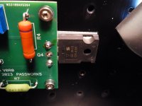
Thanks for all of your help.I disconnected the DC power from the right channel and removed the left board from the heat sinks to check values the pots are Bourns P102 and 428CO. I then replaced the boards just using the Mosfet mount bolts and started the checks as per Nelsons instructions and Voila there is bias voltage.Not sure what I did but the voltages dialed up nicely and at 0.394 volts equally across both resistors there so far is 0 volts offset and the heat sinks are slightly warmer.Progress may take a while but thanks for all of the advice.I will report back when the left board is powered up and checked.the right heat sinks are at 32 degrees centigrade and the right is at house ambient of 20.4
Attachments
90% of the battle on SMD soldering is lining up the part first, before even picking up the iron. Apply flux to pads. Line up the part perfectly in position by holding it with tweezers in your dominant hand and something sharp and pointy (like a cocktail skewer or something) in your non-dominant hand by gently holding pressure on the component from the very top, center, straight down, keeping the part in perfect position. Set tweezers down, grab soldering iron and put a small amount of solder on the tip. Tack solder one side of part. Remove pointy tool. Solder other side of part. Touch-up / resolder first side if needed. Clean up muck and crud with IPA / acid brush, etc.
Attachments

I'm in the process of converting my pseudo-F5/T (Its a combination of F5 and F5 Turbo variants) boards to F5m

Meanwhile converting my F5T V2 project to F4... only downside is I won't be able to use my trafo I made for the F5T
Meanwhile converting my F5T V2 project to F4... only downside is I won't be able to use my trafo I made for the F5T
I plan to use two Meanwell LRS-150-24, just like Lynn's post here suggests. I also have 4qty AmyAlice DC filters I plan to use if that's not overkill. I was just planning to follow Lynn's schematic in his post #76.

Before I start wiring and power up, is there an issue using four AmyAlice SMPS filters with the two Meanwells vs just using two AmyAlice filters? I'm guessing two will work fine, but I have four, so it seemed like it couldn't hurt as long as I properly connect the grounds.
I'm also curious of any progress on Meanwell filter boards as @6L6 posted a while back.
At one point it was mentioned the SMPS shutdown after extended use in the suggested configuration. Has there been any understanding as to what caused this and if any specific tweaks/mitigations can be done? I ordered two 24V 40mm fans just in case they are needed (hopefully not).
Attachments
@Jacruzer787 pointed out to me that I may need to flip the capacitors around for the two AmyAlice filters used with the V- rail. I didn't see that in @lhquam 's schematic. I'm scratching my head a little to try and figure this out and wanted to post the comment in hopes someone else can help me out with this.
I'll be using two Meanwell LRS-150-24 SMPS with 4 AmyAlice filters based on the diagram Lynn posted (#76 of this thread), which shows two filters below.

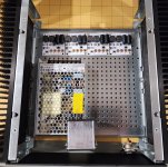
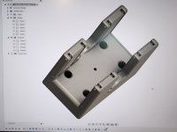
I whipped up a little 3D printed "AmyAlice Filter Rack" that will use the center hole as the "star ground" point using a bolt that won't be in contact with the chassis. I'll use a CL-60 from the star ground to chassis grounding. Hoping folks can tell me if this is a viable option, or if I'm screwing things up royally.
I'll be printing this in TPU so there's a little flex in case my dimensions are slightly off. It's a 10 hour print, so I won't know if things fit right until late tonight.

I'll be using two Meanwell LRS-150-24 SMPS with 4 AmyAlice filters based on the diagram Lynn posted (#76 of this thread), which shows two filters below.
I whipped up a little 3D printed "AmyAlice Filter Rack" that will use the center hole as the "star ground" point using a bolt that won't be in contact with the chassis. I'll use a CL-60 from the star ground to chassis grounding. Hoping folks can tell me if this is a viable option, or if I'm screwing things up royally.
I'll be printing this in TPU so there's a little flex in case my dimensions are slightly off. It's a 10 hour print, so I won't know if things fit right until late tonight.
Attachments
Last edited:
@Jacruzer787 pointed out to me that I may need to flip the capacitors around for the two AmyAlice filters used with the V- rail. I didn't see that in @lhquam 's schematic. I'm scratching my head a little to try and figure this out and wanted to post the comment in hopes someone else can help me out with this.
I'll be using two Meanwell LRS-150-24 SMPS with 4 AmyAlice filters based on the diagram Lynn posted (#76 of this thread), which shows two filters below.
View attachment 1402534
I whipped up a little 3D printed "AmyAlice Filter Rack" that will use the center hole as the "star ground" point using a bolt that won't be in contact with the chassis. I'll use a CL-60 from the star ground to chassis grounding. Hoping folks can tell me if this is a viable option, or if I'm screwing things up royally.
I'll be printing this in TPU so there's a little flex in case my dimensions are slightly off. It's a 10 hour print, so I won't know if things fit right until late tonight.
View attachment 1402540
Hello. I have asked to chatgpt and it said to isolate one of the chasis of Meanwell LRS24-150 (says negative supply should be isolated or there may be distortions and unwanted current) . It seems you did not isolate and 2 of them are connected to the case.Will it be any problem? And sorry i could not supply 1uf feedthru capacitor in my country. Can i use polystyrene or film or ceramic capacitor instead? Will it make any benefits there? What will be the value i need?
@Veysel
I'm pretty sure you need the feedthru caps for AmyAlice. Probably best to ask in the AmyAlice thread.
https://www.diyaudio.com/community/...d-assembly-max-3a-max-48v.405099/post-7891085
I hooked up my SMPS to 4 AmyAlice with star ground per the schematic I made (based on Lynn's original schematic). My F5m SMPS sounds fantastic and I didn't hear any "distortions".
https://www.diyaudio.com/community/threads/f5m-kit.408290/post-7891995
- Home
- Amplifiers
- Pass Labs
- Pass F5m