Hi all, I have built a dul mono design F5 turbo v2 and have a question regarding wiring primaries in adjacent Antek transformers. Should the primary coils be wired the opposite way to cancel out the EMI? Both transformers are in metal cases but still...
Also where would you suggest to connect ground for both channels? Poor me did not connect grounds before so both channels were basically connected through interconnects at the source and I think this was a reason for oscilating that burned like 3 sets of power mosfets... 😀😀😀
I am using jims_audio boards which is 1 board for whole amp unlike the diyudio design with 2 boards. They basically have +GG- and signal terminals.
I have earth connected to chassis and the rest is as follows
+G- from PSU to amp Pcb from this board 2nd G terminal wire to star center point which goes to the other channel PCB, both speakers GND shields of input wires at rear panel RCA outlets, also via bridge with cl60's to earth chassis.
Do you have any suggestions how to improve this or is it mostly ok?
I bought 20 of each mosfets and have several pairs to go until I run out 🙂. I haven't connected the trafos shields yet as will need to drill and tap.
Thank you all for any input, that's my first post - been reading this helpful forum a lot lately!
except common IEC connector on back of amp and mains switch, everything else is doubled
so - fuse , NTC , xformer , bridge(s) cap bank ..... everything separate per channel;
then each channel's audio gnd via NTC to safety gnd/case
xformer's phasing - chase that only if you have hum
shields - connect them to safety gnd screw , where all safety gnd connection must be made
so - fuse , NTC , xformer , bridge(s) cap bank ..... everything separate per channel;
then each channel's audio gnd via NTC to safety gnd/case
xformer's phasing - chase that only if you have hum
shields - connect them to safety gnd screw , where all safety gnd connection must be made
Thanks for a fast reply oh Guru!
that's how I had it (besides small little short I found on RCA to the chassis oops) - with the shield of the input wire from RCA to amp PCB connected on both sides... not sure if this was the case
now I just want to make sure all is dandy before I burn some more silicone
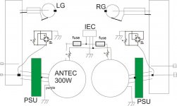
this is how I have it:
Not sure how to handle the LG and RG - please help? Wire the m together or not and how to link to PCB power/signal ground
Thanks!
that's how I had it (besides small little short I found on RCA to the chassis oops) - with the shield of the input wire from RCA to amp PCB connected on both sides... not sure if this was the case
now I just want to make sure all is dandy before I burn some more silicone
this is how I have it:
An externally hosted image should be here but it was not working when we last tested it.
Not sure how to handle the LG and RG - please help? Wire the m together or not and how to link to PCB power/signal ground
Thanks!

this is a regular coax cable 1 wire plus shield
I assume that best to connect shield to earth but how to connect grounds from RCA connectors and do I connect them together at the back panel?
Otherwise the ground will be propagated via the source of the signal and interconnect...
How to connect LG and RG and is the rest OPTIMAL ???
Thank you!
What should I do with RG - right ground and LG - Left Ground
oh I see the new picture 🙂
thought it was the same just reformatted...
Thank you a lot!
SO... I leave the 2 bridges with NTC from AMP GND as it was, also the input signal cables how I had it initially...
I actually have a Soft Start board before the transformers (sorry just one fuse 4A which I actually blew 2 times while disaster struck) so no change there either:
SO basically the only variables changed in my setup would be:
1. Transformers screens connected to chassis EARTH
2. Eliminated short on 1 RCA ground to chassis (back panel may have been lose from chassis so not sure)
3. I had all components offset like 5mm above PCB now I mounted them flash
4 The only other reason I may think of that my PCB's were burning one at a time is that maybe I tried to run them without the power ground from AMP PCB connected to bridge/NTC to the chassis at some point but not sure
Does any of the above may even seem like a probable culpruit?
Either way IN THE ABOVE suggested by ZEN MOD diagram the grounds of both channels are connected only at source - nowhere close to the power amplifier?
Are you pretty sure it is OK?
Thanks!
Last edited:
NO !!!!this is a regular coax cable 1 wire plus shield
I assume that best to connect shield to earth .................
a coaxial signal cable is a two wire connection. The core carries the Signal Flow current from the Source to the Receiver.
The screen/shield carries the Signal Return current from the Reciver to the Source.
For minimal interference these two current routes must have VERY LOW LOOP AREA. That requires you to connect the core and screen very close together to the input socket and requires you to connect the core and screen very close together at the Receiver circuit PCB.
You do NOT take the screen to some remote location and incorporate a BIG LOOP in your signal route.
ok, thanks, since I had it like this in the beginning I will assume that all disasters happened due to some execution errors, I will post my experiences soon...
thanks for now...
thanks for now...
- Status
- Not open for further replies.
- Home
- Amplifiers
- Pass Labs
- Pass F5 dual mono transformers wiring, ground design