Hi,
Does anyone knows where I can source PCB for F2J ?
Is there any interest in these amps or it is a blast from the past and there are better designs available without NFB?
K
Does anyone knows where I can source PCB for F2J ?
Is there any interest in these amps or it is a blast from the past and there are better designs available without NFB?
K
If you remove the parallel resistors it becomes a true current source which is nice. It is weak but with sufficiently efficient speakers it is magic. I use F2 inspired amps (CCS swapped with a big inductor for double efficiency) for my tweeters and would use for my mids too but for those I need more power than the F2 can offer.
I believe the OP is planning to use Lowther drivers, and my own experience
is that they want a finite source impedance, on the order of 10 ohms or so.
I will suggest the De Lite, using one of the Ixsys depletion mode parts.
The circuit is simple enough that no pc board is needed.
Of course, much caution is required to work with 100V DC....
is that they want a finite source impedance, on the order of 10 ohms or so.
I will suggest the De Lite, using one of the Ixsys depletion mode parts.
The circuit is simple enough that no pc board is needed.
Of course, much caution is required to work with 100V DC....
Attachments
It is a Lowther Dx3 in a horn that I will be using these amps for. I don't need a lot of power.
De lite was one of my consideration. But having a light bulb is not something I could live with.
I wish there was a board available. I can try to make one if someone help me with layout. But I wanted to know if there is any readymade options available.
De lite was one of my consideration. But having a light bulb is not something I could live with.
I wish there was a board available. I can try to make one if someone help me with layout. But I wanted to know if there is any readymade options available.
If I understand the project correctly one could use a 20 ohm 40 watt resistor but it will have to be mounted on the heatsink. At least I believe a 40 watt would be sufficient.
I see the point , more power with higher distortion and some high voltages. Other than lower power (10W) is there any other issue with F2J?
So to be clear , what Iam looking for a non negative feedback( global) single ended design. Is Delite qualifies for it?
Schematic pictures courtesy of Mr.Pass
Version 3 without input capacitor and his psu voltage is + 65V "only".
Psu 80V or 100 V rated cap's incrase diy project co$t i know that 😀
Interesting single-ended amp. Best regards
Version 3 without input capacitor and his psu voltage is + 65V "only".
Psu 80V or 100 V rated cap's incrase diy project co$t i know that 😀
Interesting single-ended amp. Best regards
Attachments

Just need to confirm a few details with that circuit (version 3). I'm not sure if my brain is having a melt down or not.
Assuming 120V mains then a 300W globe should have the following resistance (approximately).
P=VxV/R
R=120x120/300 = 48 Ohms
1.6V drop across R4 indicates 1.6A through the circuit.
1.6A across 48 Ohms = 76.8V drop across the globe.
If power supply is 65V, amp will not function as desired.
Should the circuit have two light bulbs in parallel or where did my brain crash and burn?
The Burning Brain Festival.
Hahaha
Last edited:
Bulb's resistance is not constant - it depends on current i.e. temperature.
When you connect 300W bulb to 120V it will draw 2.5A. With 1.6A it will run cooler and its resistance will be lower.
When you connect 300W bulb to 120V it will draw 2.5A. With 1.6A it will run cooler and its resistance will be lower.
Last edited:
Schematic pictures courtesy of Mr.Pass
Version 3 without input capacitor and his psu voltage is + 65V "only".
Psu 80V or 100 V rated cap's incrase diy project co$t i know that 😀
Interesting single-ended amp. Best regards
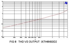
I was reading about this amplifier last week and I priced the caps for the 100V version and it is exactly as you said, very pricey for a cheap diy'er as myself but I am sure it would be worth it. I am debating about the schematic you posted using 65V version but I favor using a resistor vs light bulb. Mainly because it is easier to build in a case with a resistor. The graph should not discourage builders because I have many SET's with similar graphs and they are some of my favorite amps, with horns. Remember we are talking 2nd harmonic from Nelson's article.
Last edited:
- Status
- Not open for further replies.
- Home
- Amplifiers
- Pass Labs
- Pass F2(J)