it's easy to calculate dissipation in series mosfets - standing current multiplied with difference between in and stabilized voltage
thus even one IRFP mosfet will do
again - it's better to go with cap multiplier - variations in mains voltage isn't so important , you'll loose less voltage at series mosfet and have practically same or even better sonic results
it's absolutely crucial to keep D-S voltage of IXTH... at prescribed 25V or so , to keep dissipation in safe area
You can try this, I modified an existing model to approximate the datasheet curves, no attempt to get the capacitance etc. correct:
Code:
.MODEL IXTH6N50D2 VDMOS(KP=3.0 RS=1m RD=.49 VTO=-2.4 RDS=20E6 Lambda=0.008 subthres=5m CJO=4.9n M=1.5 a=1 CGDMAX=900p CGDMIN=80p CGS=6200p a=1 VJ=2.6 RG=10m IS=1.37u N=2)Thanks!You can try this, I modified an existing model to approximate the datasheet curves, no attempt to get the capacitance etc. correct:
Code:.MODEL IXTH6N50D2 VDMOS(KP=3.0 RS=1m RD=.49 VTO=-2.4 RDS=20E6 Lambda=0.008 subthres=5m CJO=4.9n M=1.5 a=1 CGDMAX=900p CGDMIN=80p CGS=6200p a=1 VJ=2.6 RG=10m IS=1.37u N=2)
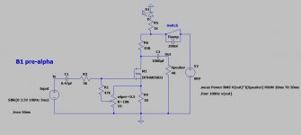
With your help and Nelson's two designs: FAOW & De-Lite, I was able to design the most simple amp I can think of.
Attachments
I've been playing with this design more and more in LTspice. I've run into a problem simulating the incandescent light bulb. My Google-Fu is not leading me to the answers I seek.
Going back to the original De-Lite design (forget my above post) Pass describes the 300W light bulb as "about 20 ohms". I figure the resistance changes as it lights up. On my multimeter, cold it's at 4.4 ohms. He also states you could substitute it for a 16 ohm power resistor. Trying these values out in my simulator results in wildly different outcomes. Which led me to my next question: what does the resistance curve of the light bulb look like as it lights up? Without this knowledge, I can't really progress further in simulation. I suppose I could just build it, but the power supply requirements look insane depending on what values I plug in. It's making me second guess high power Class A designs and makes me curious about Son of Zen and then into the dark side--Class AB, push-pull, etc.
FWIW, I built a version my above design and it performs really well...at only about 1.5 Watts RMS. I'm looking for more like 10-25 Watts now, 50 Watts being my pipe dream.
The resistance goes up as the filament gets hotter - 4 ohms cold becomes
22 ohm dimly lit and from the 300 watt 120V rating we infer that it is 48 ohms
at 120V.
22 ohm dimly lit and from the 300 watt 120V rating we infer that it is 48 ohms
at 120V.
Alright, so now I assume there is a curve from 4.4 ohms cold to 56 ohms @ 130V on my light bulb (rating on the box). I've seen charts that suggest an S-curve rather than linear or log, etc. I'm just wondering where I would end up on that curve? 22 ohms is dimly lit because of PSU voltage? Current draw through the mosfet? Could I assume 25-ish ohms for my slightly different 300 Watt light bulb? Rating: 120V 266 Watts, 130V 300 Watts...then I'm using ohms law...
One last question. The light bulb does not act as an inductor, correct? Otherwise I would like to sim with a choke and some Henry value there I guess.
One last question. The light bulb does not act as an inductor, correct? Otherwise I would like to sim with a choke and some Henry value there I guess.
you can approach that from two sides:
- either shoot for desired Iq and voltage across active part , having rail voltage on mind , then search for bulb having adequate resistance in situ ....... or
- see what you have of bulbs , having on mind Iq and possible rail voltages, choose one , then build from that
in both cases you're taking bulb as sorta fixed resistance , counting on heavy steadiness of heavy Iq in A Class amp
practically - if you choose bulb with more W , having adequate resistance in your point of interest , it'll have greater level of inertia than wimpier bulb (also having adequate resistance in same conditions (
at least that's my logic
if you have a luck to have I/U graphs for bulb...... or invest some time in making your own .... if inertia is main goal , then it's logical that you want to put it to work in area of most horizontal part of U/I characteristic
and - don't forget that important part of DeLite approach is having fun ...... you can even use filament of some gargantuan toob as load resistor
Thank you Nelson and Zen.
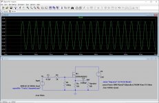
The sims are coming up pretty good with your help. My load is 4 ohms because this one will be powering an SVT 6x10" bass cabinet. This sim did just over 10 Watts RMS.
I never simmed the bias adjusting pot until now. I believe it might be the key to help me with a somewhat unknown resistance value of the light bulb and PSU voltages. Still, this thing is a beast as far as power requirements go. Viva la Class A! lol
Attachments
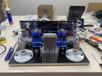
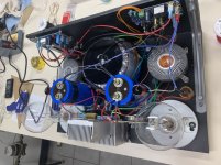
I am having a hum/buzz problem though. It was built almost exactly like Fig 5 with 60v supply. Its a 60Hz hum with many other noise components that make it sound like a buzz. Only thing different is the input caps are Audyn 6.8uF pp. The buzz is not volume dependent, so if you play music loud enough it'll cover the buzz, and the noise is there whether RCAs are plugged into source or not. I ordered a 2mH air core which I will replace R1 in the pi filter with. I also got some line caps to put across the rectifier. If that doesn't get rid of the noise, any other suggestions?
Well the CPU fan heatsinks are at 110*F after half an hour......If I need to I did buy some low speed 21db AC fans I can put on the sinks.
Am I correct in assuming that is your star ground adjacent to your transformer? The hum may be coming from the magnetic field cupping to those wires being that close to it and the ground point. IMO that would account for it not varying in volume with input signal modulation or the gross volume level. Just a thought. Also digging the cpu fan solution, mind if I borrow that?
I have tried two different kinds of fans, 12v CPU fans and 120v (21db) AC fans and both are too loud. The AC fans are far too loud, running at 51db in reality. The CPU fans are quieter but running at full 12v you can still hear them from listening seat. I am going to rebuild the amp and use a pair of large heatsinks instead.
I have discovered that the Delite amp is fact almost completely quiet and free from hum, with no source plugged in you can barely hear any hum even when your ear is against the speaker. When I plug in my source, the BA-3 preamp, I get hum and buzz, but only when I am using a Mac Mini/Audioquest Dragonfly as the source. The record player has only a tiny bit of hiss. Every component in my system except the Mac Mini has a ground wire and is plugged into the same Monster filtered surge protector and therefore into one outlet. I think I just need to figure out how to ground the Mac Mini.
I have discovered that the Delite amp is fact almost completely quiet and free from hum, with no source plugged in you can barely hear any hum even when your ear is against the speaker. When I plug in my source, the BA-3 preamp, I get hum and buzz, but only when I am using a Mac Mini/Audioquest Dragonfly as the source. The record player has only a tiny bit of hiss. Every component in my system except the Mac Mini has a ground wire and is plugged into the same Monster filtered surge protector and therefore into one outlet. I think I just need to figure out how to ground the Mac Mini.
If the Mac Mini is isolated from AC ground, you should not have a ground loop issue.
Anyway, some experimentation usually isolates the issue, and you seem to be
able to do that.

Anyway, some experimentation usually isolates the issue, and you seem to be
able to do that.
The 12V fans you tried are not exactly what one could call a quiet example of that breed if they are that loud at full speed.
Noiseblocker NB-eLoop B12-1 120mm Bionic Loop Fan, 800RPM, 33.73CFM, 7.83dBA - Newegg.com
Is an example of a fan labeled ‘ 120mm Bionic Loop Fan, 800RPM, 33.73CFM, 7.83dBA’, that I would consider for myself. 800RPM is the maximum rpm for the model.
There is a passive cooler that can dissipate 95W without a fan, and up to 150W with a fan that may also be worth looking into as a solution.
Wait..., I have an unused cpu water cooling rig..., the wheels are a turning here..., used light bulb sockets and old computer water cooling bits...., see if I can match up four of these couple dozen 20N50’s.
I am using a series crossover with my OB and have three versions of the venerable Dynaco 70, an original, one with a tubes4hi driver board personally stuffed with goodies, and one I bought already modded with a volume control and other goodies, as well as an original GFA 555; the delta 15A woofer works better with GFA 555 and the headroom in the mids is noticeable with its full range driver as well, so a deliteGFAl merging may be in order.
- Home
- Amplifiers
- Pass Labs
- Pass "DeLite" Amp from BAF