Hi all,
I've assembled my B1 buffer, powered it up, and I only get sound coming from one side (left channel). I have tried swapping leads and used that process to identify which input channel works.
I only have a multi-meter and don't really know what I need to be inspecting to see which component may have failed (if indeed there is one which has failed).
Please let me know what photos or information I can provide which will help with fault finding. I am open to suggestions too, in case there's a process or something I can apply to further investigate where the fault is occurring.
Thank you all in advance 🙂
Regards,
Vlad
Did you use the PCB or point to point?
Either way, first check continuity from the power supply output to the top(drain) of the top fet
Either way, first check continuity from the power supply output to the top(drain) of the top fet
Last edited:
If you have continuity there then go to the fet datasheet and make sure it is oriented correctly
edit:
Now I realize you can probably just compare jfet orientation between working and non working side.
Where did you get your fets and have they been matched or otherwise tested?
edit:
Now I realize you can probably just compare jfet orientation between working and non working side.
Where did you get your fets and have they been matched or otherwise tested?
Last edited:
If you have continuity there then go to the fet datasheet and make sure it is oriented correctly
edit:
Now I realize you can probably just compare jfet orientation between working and non working side.
Where did you get your fets and have they been matched or otherwise tested?
I purchased the PCB and jfets from the pass website. I am assuming they were tested and working.
I had similar problems. I just took everything apart and resoldered according to the schematic. Mine was point to point so it was easier to desolder. Worked like a charm afterwards. Still have no idea what went wrong.
So either a part is bad or the board is bad... but I would hope the PCB is fine.
If you have tested the things suggested above you could try to see if you need to reflow any component legs, or just reflow them all.
And you might want to measure the resistances of the resistors to make sure you haven't switched them accidentally. Also make sure the capacitors are oriented with the + where it should be (if not they can get burned out) and have infinite resistance across them.
A really dumb question: Are the jfets all 2sk170 or 2sk370?
I only ask because I recently saw a thread where it turned out the
wrong jfets were sent.
Good luck.
Dennis
I only ask because I recently saw a thread where it turned out the
wrong jfets were sent.
Good luck.
Dennis
A really dumb question: Are the jfets all 2sk170 or 2sk370?
I only ask because I recently saw a thread where it turned out the
wrong jfets were sent.
Good luck.
Dennis
I just checked they are all 2sk170s. Thanks though
I had the same problem on a tube build yesterday. I took some resistance readings of both channels at connection points comparing the two channels and found my problem. Most problems are incorrect parts or cold solder joints. Take your soldering iron and go over all the joints of the bad channel. That is the first thing I would do. I played around with some of the Chinese assembled boards a few years ago and the ones I bought that did not work right worked fine when I did this.
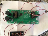
Take a picture from above which shows clearly, all the wiring, to both volume pots as well as rca plugs, etc. There really isnt much to go wrong.
Russellc
Russellc
I'm guessing it's the wiring of the volume pots as well. They are not the same left to right, they are mirrored.
Take a picture from above which shows clearly, all the wiring, to both volume pots as well as rca plugs, etc. There really isnt much to go wrong.
Russellc
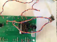
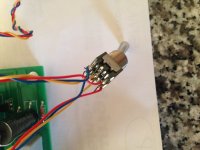
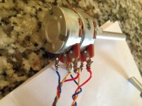
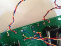
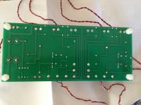
Hi Russell, please see the photos taken of the board and associated connections from both sides. Please let me know if you want any close-ups.
Attachments
Last edited:
The photos didn't post...
Sorry I don't know what went wrong there. Check above, the photos seem to work now. Really appreciate your/everyone's input, I'm sure it's something silly and simple but I just can't seem to pick it! 🙂
The pot connections on the PCB are backwards on the side closer to the electrolytic capacitors. Good guess Kevin!
Swap the red and blue.
Swap the red and blue.
You guys are absolute champions! I can't wait to get home and try this. I can't believe how silly of a mistake I've made, so so silly! 🙂 But you guys are the best! I can move on and build the DC power supply for this now, and then move on to the DAC. Thank you
What are you using for your power supply?
From memory its a 24VDC power-pack style supply. I'm going to get a universal PSU for it when I mount the whole arrangement inside a case. Any recommendations? Will it add any value by way of sonic performance?
- Status
- Not open for further replies.
- Home
- Amplifiers
- Pass Labs
- Pass B1 Buffer Preamp help
