Thanks for the replies, it's always a pleasure to get the constructive feedbacks, particularly from Mr. Pass.
I seen a thread somewhere on this forum where someone used an A40 frontend configuration to drive a set of Aleph output devices. Is this trickier then it sounds on the surface to accomplish?😕
I have all of the devices for an A40 including the boards. I haven't look at it closely yet, but I will. If I remember correctly, the A40 had darlington differential inputs with a JFET current source. Would this be sufficient to drive the set of three 240's?😕
Thanks,
Rodd Yamashita
I have used the A40 board to drive a tripple darlington BJT output stage and Lateral MOS, but do not think it is suitable for the IRF devices.
Pass amp way too noisy
Rodd,
I would like to hush your concerns regards noise.
Hum
In my setup (see pic of JBL Large format monitor speaker in biamp post) there is only discernable hum via the woofers at ground zero (100 hz I suspect).
Hiss
With my ears literally in the throat of the horn I can only just hear faint hiss (I do this reluctantly you can asppreciate why!!!)
My Aleph 5 uses +- 60,000 uf filter bank.
Asimple means of further reducing any trace of ripple would be to use a choke as desribed else where my Mr Pass (ie C+2MH+C).
Added noise from the BOSOZ is minor and I would expect most of your noise in the bi amp system to come from the electronic crossover.
As Mr Pass says, with plenty of speaker sensitivity just shave of some with a pad.
regards
macka😛
In my Aleph 5, biased with about 2.5 Amperes, the main contribution to the output noise is a 100 Hz hum, hence a power supply noise.
The capacitor bank is made by 132000uF per channel.
I've noted a 6 dB PSU noise reduction using an RC net (220 Ohm + 220uF) to filter the B+ rail for the first stage.
The cold side of the capacitor must be connected to the B- rail, near the R14's cold pin (in the A5 schematic).
With those values, the power on bump is almost the same.
Marcello
Thanks for the feedbacks,
My plan is for an Aleph 5 configuration with 6 output devices/channel operating at about 2amps of bias (per set of 3), but at a lower voltage (about +-28vdc). I have all of the parts for the power supply including the inductors for the PI filter. I will also place hi-voltage caps across each of the bridge diodes.
Marcello,
If you don't mind me asking, how did you implement the RC filter? Is it just a resistor in series with the capacitor across the + and - PS rails?😕
I seen another thread that spoke about zener noise. Mr. Pass had suggested to use 1/2W zeners instead of 1W'ers. There was also a suggestion of adding a cap across the zener. I'm assuming that Z5 in the Aleph5 would be the zener of that discussion. Would a .1uf cap be an appropriate value placed across this zener?😕
I believe I will try these tweaks first and see how it turns out.
Thanks All
Rodd Yamashita
Yes, Rodd, but I've made a mistake: the capacitor was 100uF 100V, with 220uF the power-on bump slightly increased.
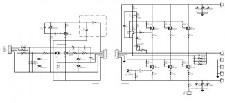
I also bypassed the current source zener with 0.1 uF metal film capacitor, but I'm not sure if this is a proper value.
Anyway, you can see the RC filter in the dashed box.
I found some Motorola zeners, employed as input-clippers, that where quite noisy - the noise floor could be seen by an ocilloscope! - , but if this happens, I think that the bypass capacitor is not able to correct this failure.
Marcello
Attachments
Zener Noise and filtering
If the voltage to the front end current source is filtered too much you will have a hell of a turn on thump as the current sources for the output connected to the positive supply will come up before the current from the input stage and the output Mosfets to the negative supply.
The same result will occur from putting a large cap across the 9.1V zener reference for the current source. The solution? Use a LM329 voltage reference with a 0.1uF cap in parallel with it. The voltage is 6.9 volts so you will have to change the 221 ohm source resistor the get the same bias current for the front end.
The LM329 is very quiet and the AC impedance is over twenty times less than a zener for much better supply rejection. You can also also change the resistor that biases the LM329 (R10 on Aleph 5)to provide 1mA of current to it to get even more supply rejection. R = (Vpos-6.9) divided by 0.001. It is also much cheaper than the woofers you are going to eat by filtering the front end supply or zener.
http://www.national.com/ds/LM/LM129.pdf
H.H.
Re: Zener Noise and filtering
It should be R13. The LM329 can work from 0.6~15mA. (45-6.9)/10k=3.8mA. The orignal design will be ok.😛
You can also also change the resistor that biases the LM329 (R10 on Aleph 5)to provide 1mA of current to it to get even more supply rejection. R = (Vpos-6.9) divided by 0.001.
It should be R13. The LM329 can work from 0.6~15mA. (45-6.9)/10k=3.8mA. The orignal design will be ok.😛
LM329 bias
R13 (10K) for Aleph 5. I used 1mA since that is the range where the LM329 is specified for the parameters in the data sheet, the math is easier (no calculator required), and I never use a part at the bottom or top end of it's range. Some one will pick the nearest 5% resistor value or the line voltage will be low one day and the part will drop out of regulation. Always use a little margin for error for changes in operating condition and parts tolerance!
"The orignal design(resistor value?) will be ok."
The whole point was to pick the minimum current and therefore the largest bias resistor value. This gives the greatest rejection of supply noise for the voltage reference. I would think one would want to do this right if he was going to go through this much trouble and we are talking a threefold or greater rejection ratio for the same parts count. A no brainer as they say.......
H.H.
With the values as above (220R + 100uF) the power-on peak increased less than 5%, as I could see by mu storage scope.
Marcello
Marcello
power-on peak
Yep and someone will go stick a 1000uF in there and bottom thier woofers on power up. Just wait......
H.H.
Yep and someone will go stick a 1000uF in there and bottom thier woofers on power up. Just wait......
H.H.
1000uF
You have never heard of the if X uF is good 10X uF would be better theory of power supply design. It is very popular in the US where we tend toward excess in everyyhing we do. My woofer warning still stands for the less cautious out there.....
H.H.
You have never heard of the if X uF is good 10X uF would be better theory of power supply design. It is very popular in the US where we tend toward excess in everyyhing we do. My woofer warning still stands for the less cautious out there.....
H.H.
THEROY is not everything....
Why you said 10X uF, why not 1000X uF or 1000000X uF. You only based on THEORY to make an audio machine?? There are so many tricks....
Why you said 10X uF, why not 1000X uF or 1000000X uF. You only based on THEORY to make an audio machine?? There are so many tricks....
Harry,
Have you ever used it before in this configuration? Did it perform up to the spec's?😕
Marcello, Harry,
I won't bottom my woofer out 'cause I promise not to go more then 2X... er... maybe 3X.😀
Actually, I will be driving a pair of JBL LE85 horn drivers directly from this amps outputs. 5% of 50W starts to seem a bit much at 2.5W into a pair of horns. Although they won't hurt the horn drivers that can take 10X 2.5W, I would get a very rude turn-on spike of well over 100db. I may be able live with it if I had to since I leave my system on 24/7. I'll have to think about that one.
Thanks,
Rodd Yamashita
What a cool device😎...The solution? Use a LM329 voltage reference with a 0.1uF cap in parallel with...
Have you ever used it before in this configuration? Did it perform up to the spec's?😕
Marcello, Harry,
...and bottom thier woofers on power up...
I won't bottom my woofer out 'cause I promise not to go more then 2X... er... maybe 3X.😀
Actually, I will be driving a pair of JBL LE85 horn drivers directly from this amps outputs. 5% of 50W starts to seem a bit much at 2.5W into a pair of horns. Although they won't hurt the horn drivers that can take 10X 2.5W, I would get a very rude turn-on spike of well over 100db. I may be able live with it if I had to since I leave my system on 24/7. I'll have to think about that one.
Thanks,
Rodd Yamashita
- Status
- Not open for further replies.
- Home
- Amplifiers
- Pass Labs
- Pass' amps way too noisy?