Thanks Norb. These measurements will be a good reference for comparison. Thanks for the advice on the Gate resistors. Somewhere there's a defective part. since everything seems to check out before connecting the output I guess I'll start there. I did check everything with the scope. too late to start again today but I'll take some pictures of the scope readings in the next couple days and post them. I haven't done enough of this to recognize what's normal and what's not.
Thanks for the advice.
Dan
Thanks for the advice.
Dan
"Connected the left channel output and measured ac ripple at the PS Caps.
Pos = .06 vac, Neg=.185vac ( a little better than before, was at .240)"
Have you looked at the output from the regulated front end PS? I recall there was some ripple in my front end power supply when under load. Some of the components got very hot over time (judging by the bulged caps and the brown marks under the diodes). Perhaps there is a component there that is not performing correctly.
JJ
I did measure the ripple on the reg PS at the connections to the frontend - Pos measured .007/.008vac and the Neg measured .013/.020vac. When I repaired the Reg supply, which is where this project started (10R on the voltage doubler was bad), I did notice lots of discoloration around the AC components, no doubt due to heat. But the power supply didn't seem to draw excessive current when I ran through the tests (see earlier post). They seemed to be reasonable, assuming 1vac is what it should be.
I'm a little surprised to see different ripple voltages on the channels connected to the same regulator. Sounds like it might be an oscillation issue. What did you change about lead dress?
Does the AC noise at the drive terminals go away with the output stage disconnected/at minimum bias? You may still be dealing with a ground loop.
Does the AC noise at the drive terminals go away with the output stage disconnected/at minimum bias? You may still be dealing with a ground loop.
I did add some 100uf, 100v caps I had in the parts box to the front end. Prior to getting in to this I only had .47uf bypass caps at each PS connection. Since it's an easy test I'll start by taking them out and remeasuring. The other change I made was to redress the AC cables that run from the back of the chassis to the trans located up front. The AC, LED, and switch wires are all bundled together with plastic wire wrap. I also disconnected the RC filter across the switch. I'm not sure it added much and I didn't care for the constant small voltage it generated. When I get home tonight I'll try the PSU changes and post the results, and maybe some pics of the scope if things don't look any better.
Dan
Dan
If you are using the LED as indicated on the schematic, you now have leads connecting to the regulated supply bundled with your AC lines. You might try moving the LED leads out of the AC bundle.
Excellent point!!! It never occured to me this could be a problem. I'll reroute the LED wiring and see if that helps before going any further. It sure can't hurt. I had it routed with the AC before but in the process of bundling all the wires together things may have changed.
I went back tonight and unbundled the AC from the LED, retested and remeasured the front end with the MM and the scope. Took some pics which I intended to post along with the measurements but they didn't turn out - you can't see the trace because of the lighting. Anyway the AC on the Reg supply rails on both channels dropped down to 0vac. Good news. And the buzz in the speakers is almost gone completely but I did drop the bias to 250mv per device which is to about 50W rms. Now the AC on the mains caps. The Pos rails still measure .006/.007 vac. The Neg rails are still high - .180/.210 vac. On the scope I can't tell the difference between the +/-. They just look like an upside down V for the most part. I haven't mentioned but these are only 20,000uf caps so I guess I'd expect the AC to be a little higher than usual, just not the difference between the +/-. The frontend output on the scope isn't perfect and is identical with the output connected. It's shows a slight 60hz wave with some noise spikes undoubtedly noise with sensitivity set at .1v/div. Wish it was better and suggests the frontend needs more attention. Not sure where to go next. I've replaced alomost every component on the frontend already aside from a few of the zeners, which may be the source of the noise. I may try some different grounding setups ...again. and see if I can come with a solution that flattens out the tracel a bit. for now guess this will do. down the road ...maybe upgrade to some new larger caps.
I'll try taking some pics again tomorrow night and post them.
I'll try taking some pics again tomorrow night and post them.
I threw together a quick sketch of my ground scheme this morning hoping someone might point out where I went wrong. I'm working from memory so hope I have everything. As my wife reminds me I can't draw worth a darn.
Thanks again for all the help and support.
Thanks again for all the help and support.
Attachments
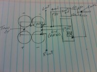
The input grounds should meet at a star with the front end ground and zoebel grounds. Right now you have them isolated by the diode//R. If you have XLR connectors Pin 1should go straight to the case, but the rest of the circuit's grounds should be on the other side of the ground loop breaker.
As long as I keep the input, frontend and zobel grounds together does it matter which side of the diode/R they're on? Up until last week I had the input ground connected to the same star as the frontend and zobel.
The diode//R is a ground loop breaker. It is only necessary IF there is a problem. Theoretically you should be able to ground all equipment to the chassis star. Suggested reading David's grounding article Audio Component Grounding and Interconnection - diyAudio
Last edited:
Thanks Bob. Took a quick glance at this article and it seems to be just what I've been looking for. Will give it a read. I'm sure all the answers to my questions are in there.
Thanks again for all your help.
Thanks again for all your help.
Great read!! A lot to digest but it really helps you put things into perspective when it comes down to execution. While primarily interested in gaining a better understanding of grounding the chapter on noise control also caught my attention. I never thought about the noise contributed by the bridge and triac. I recall you pointing out a while back the triac can be eliminated by using an appropriately rated AC switch....one less source of noise. Those Bulgin switches look really nice and are rated for 250Vac, 5A.
On the Reg supply I did go with a fast recovery diode in the 220 package but the main bridge rectifiers are just the standard DigiKey 25A, 100V variety. Any suggestions on a low noise replacement? Just a quick browse of what's available from Digikey with a similar VA rating nothing stood out.
On the Reg supply I did go with a fast recovery diode in the 220 package but the main bridge rectifiers are just the standard DigiKey 25A, 100V variety. Any suggestions on a low noise replacement? Just a quick browse of what's available from Digikey with a similar VA rating nothing stood out.
My A75s use standard bridges and 1N4007s for the front end. I have a couple of PSUs built up for another project with MUR2020s but haven't listened to anything with them yet. I've heard of people using 4x MUR3030 with both diodes paralleled, but there are plenty of "what rectifier?" discussions in this forum.
I know this isn't the place for rambling but this story is just too good to not tell and could be useful for others. So...last night I decide to take a break, fire up the guitar and jam to some tunes on the system....kinda why I got into DIY audio to begin with. About 30 minutes later I get up to change out the CD, the room is quiet and I realise it sounds like there's a beehive in the room. The buzz in the stereo speakers is about the same but in addition my guitar amp is also buzzing like crazy. Now this amp is only 3 months old. It's a 15w Egnater Tweaker tube amp. All of a sudden the pieces of the puzzle start to fall into place. I moved my music room over the christmas holiday into a spare bedroom in the basement and while I haven't verified this yet I think the AC outlets are on a different breaker than they were prior to the move. In fact, I'm pretty sure it's the same breaker that the exterior entry door lights are on which I have long suspected may have an electrical issue since I seemed to be replaing bulbs in them every 2 months.
To make a long story short it looks like I need to start pulling AC outlets and make sure there aren't problems there. Ideally it would probably be worthwhile to run a dedicated line to the breakerbox for just the audio system...another project. Whoever said retirement would be boring. Just wish I was retired.
To make a long story short it looks like I need to start pulling AC outlets and make sure there aren't problems there. Ideally it would probably be worthwhile to run a dedicated line to the breakerbox for just the audio system...another project. Whoever said retirement would be boring. Just wish I was retired.
Have you checked the suspect circuit with an outlet tester? Less than $10 and will identify reversed connections, bad neutral and ground connections
You can test your theory with a heavy duty extension cord while SWMBO is out of the house.
You can test your theory with a heavy duty extension cord while SWMBO is out of the house.
Over the weekend I went out and bought an outlet tester as you suggested and all the outlet tested fine. The extension cord from another outlet made no difference either. Still a buzz. I checked the house earth ground and cleaned things up where it connects at the water mains entrance to the basement. It was pretty corroded. Still no change so have been doing alot of research on amp grounding keeping in mind how I have my grounds connected. The one thing that concerns me is that the Reg PSU ground is in the path to the chassis / earth ground connection, which puts it directly in the downstream path of the high current ground to chassis. If I understood what I read correctly the high current ground where the main unreg PSU caps and transformer CT is connected should be the connection point to chassis. This puts the Reg PSU, input, and frontend grounds upstream of any ground currents flowing to the chassis ground.
I realize that in the end it'll all come down to what works the best so it's becoming an exercise in test and trial. Because of the amp layout and physical distance between the AC earth ground and possible main cap/CT chassis ground points I'm wondering if it's acceptable to have the earth and circuit chassis grounds connected at 2 different points. Everything I've read states the AC Earth ground should be connected to the chassis with the shortest possible wire. Any thoughts / comments?
Dan
Sounds like a slight variation of Figure 4.8-1, using the chassis as the link between the system and safety ground. It should work. You can also isolate your system star from the chassis and use a 16 gauge or bigger connection from the star to the chassis at the same place as the safety ground.
I did some searching and didn't come across any discussion on this specifically. I was reading a discussion on CRC power supplies when it dawned on me...I wonder if anyone had ever tried using a CRC network on a Reg PSU to deal with PSU rail oscillation? I know it's used frequently on unregulated supplies to reduce AC ripple.
Hmmmmm.....
Hmmmmm.....
- Status
- Not open for further replies.
- Home
- Amplifiers
- Pass Labs
- Pass A75 Troubleshooting