Hello,
I'm a new DIY audio member interested in class D amplifiers to be used with Infinity vintage speakers.
I am using Pascal Audio U-Pro1 and S-Pro2 power amplifiers and I'm looking for a document related to the external capacitors which can be connected to these boards.
The document from Pascal Audio I'm looking for is named: "Application Note_Extra E-Caps-1_0"
Can someone share this document?
Thanks
Welcome to diyaudio!
I have no experience with this amplifier board, however power requirements for class d amps tend to be pretty universal in their application.
It is fairly common to use external capacitors when an amp board has a terminal block for the power input. There are limitations to which many switching power supplies will see this extra load as a short circuit and trigger a fault mode(shut down).
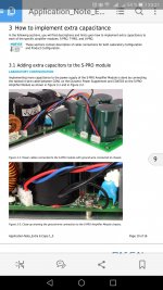
On page 9 of the data sheet for these amps, it states that optional 10K uf capacitors can be used to achieve the results shown in the graphs that illustrate the burst power from a 1khz test tone.
I have a feeling that these extra parts would only support the outer limits of the power handling and be fairly academic during normal use. There have been other class D amps where the extra capacitors have actually subjectively reduced the sound quality at normal listening levels, your results may vary...
I have no experience with this amplifier board, however power requirements for class d amps tend to be pretty universal in their application.
It is fairly common to use external capacitors when an amp board has a terminal block for the power input. There are limitations to which many switching power supplies will see this extra load as a short circuit and trigger a fault mode(shut down).
On page 9 of the data sheet for these amps, it states that optional 10K uf capacitors can be used to achieve the results shown in the graphs that illustrate the burst power from a 1khz test tone.
I have a feeling that these extra parts would only support the outer limits of the power handling and be fairly academic during normal use. There have been other class D amps where the extra capacitors have actually subjectively reduced the sound quality at normal listening levels, your results may vary...
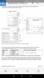
Yes 2*10000uF is the maximum recommended value per channel.
I saw those 2 pictures on another thread on this forum but I would like to get the complete document to understand the reason why 2 resistors R2 and R3 are added and what is the purpose of the optional resistor R1 also.
Are these R2 and R3 mandatory and what should be the values?
I saw those 2 pictures on another thread on this forum but I would like to get the complete document to understand the reason why 2 resistors R2 and R3 are added and what is the purpose of the optional resistor R1 also.
Are these R2 and R3 mandatory and what should be the values?
Attachments
Not mandatory, but if you did, they’re more likely to be a very small value, like .1, yet should be higher wattage. Try searching for CRC power supply to learn more about that arrangement.
This isn't a CRC-arrangement though - if it was the R's would be in series with the voltage, not in parallel. In any case using a CRC PSU doesn't make much sense here.
Laurent, the R2/R3 resistors shown are probably just "bleeder" resistors, i.e. for ensuring that the caps on the aux. board are discharged when the module is powered off. I am not sure exactly what sort of value to aim for, but most commonly I see values that correspond to around the current that an LED would draw, so app. 20mA (and you could actually add LEDs to the board if you wanted to, to show whether the caps are charged). Because of the high supply voltage you should calculate the power dissipated in the resistor because you might need a resistor rated 2-3W.
The R1 resistor looks like a ground loop breaker of some sort(?). If so, I think 10R is a commonly used value.
Last edited:
Ha! You’re correct, and it doesn’t make much sense really in this application.
I’d stick with the data sheet values more than what has been suggested by the third party manufacturer if it were me.
I’d stick with the data sheet values more than what has been suggested by the third party manufacturer if it were me.
Thanks to you both for your replies.
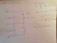
If I understand well, using leds, the resistor calculation would be like this (see the picture attached). So R2=R3=3400ohm.
Anyway, how long would it take for the leds to turn off once the power is off with such big capacitors?
What do you mean by 10R for R1?
If I understand well, using leds, the resistor calculation would be like this (see the picture attached). So R2=R3=3400ohm.
Anyway, how long would it take for the leds to turn off once the power is off with such big capacitors?
What do you mean by 10R for R1?
Attachments
- Home
- Amplifiers
- Class D
- Pascal Audio extra capacitors