this is a new setup on a amp. I have never seen this style of audio card. i havent pulled the amp completely apart yet. just trying to get a head start on parts identification.
Attachments
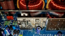
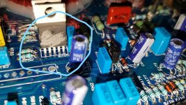
I don't know for certain. They look like the MIC4420 type drivers. Previous post:
Digital Designs Z2b driver
Digital Designs Z2b driver
upon reading the Digital Designs post and reading the data sheet i'm not sure about which ones they used. either non-inverting or inverting drivers. and if both are used which position they are used in. Or if they only use one of the two and just use double up for each set of outputs.
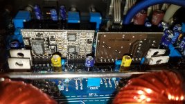
MIC4420zt non-inverting
MIC4429zt inverting
MIC4420zt non-inverting
MIC4429zt inverting
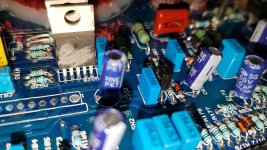
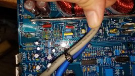
yes the ground legs do attach to the source leg of the fet they are driving.
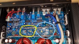
The output leg connects the set of fets through a resistor and diode that are parallel with each other. i have uploaded a pic to show what i am describing.
Even with all fets removed on this side I was showing a short between the gate and the positive rail. i removed one leg of all the gate resistors and still had the short while measuring the other leg and the rail. Ended up being D54a shorted.
Attachments
I would think that both are non-inverting.
To check (both) remove them from the board.
Connect the Vs input to 12v (via a 1 ohm 1/4w resistor to protect the IC).
Connect the ground to the 12v PS ground.
Connect the input to a 10k resistor (not critical).
When you touch the 10k resistor to the Vs input (12v) of the IC, the output pin should follow (go to 12v).
Last edited:
One without a doubt was bad. It showed to be shorted on all legs. The other passed the procedure that you gave Perry. I would still feel better replacing both as the other may be weakened. I forgot to mark the audio driver cards as to which side each came out of. So i will use the empty side where i have removed all the fets to see if i have good drive signal from each. Elderly moment.
- Status
- This old topic is closed. If you want to reopen this topic, contact a moderator using the "Report Post" button.
- Home
- General Interest
- Car Audio
- parts identify