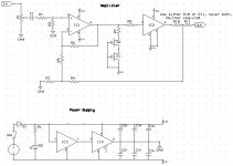
Attached is the schem for the amp I am going to build soon. Parts/values I have picked are as follows:
Power Supply:
D1- 1A, 40V schottkey
D2- Vishay/Telefunken blue water clear LED
RL- somewhere around 4.7k, probably- will test
IC3- Burr-Brown TLE2426 dip
IC4- Burr-Brown BUF634 dip (in normal bandwidth mode)
C2- Nichicon UPW series, low impedence 4700uF, 25V
C3- Nichicon UPS series, low impedence 470uF, 25V
C4- Dayton 6.8uF, 400V metallized polypropylene (perhaps polyester)
Power transformer: 24VDC type with at least 400mA. Looking at HIQ and Cincon.
Amp:
P1- for now a cheap $2.35 50k dual linear audio pot- looking for better
C1- Solen metallized polypropylene or Orange Drop- which is better?
R1- 1k
R2- 100k
R3- 475
R4- 4.75k
R5- 2.21k
R6- 221k
R7- 100
R8- 47.5
R9- not used
R10/11- not used
IC1- Burr-Brown OPA627BP
IC2- Burr-Brown BUF634 dip stacked four high in high bandwidth mode
Input jacks- Dayton gold-plated RCA
Ouput jack- 1/4" locking Neutrik
Q1/2- 2N5484 (or something like that) JFET
All resistors are Meggitt/Holsworthy 0.1%, which I am told are also called Holco resistors. Is everything ok?
Are the Nichicon caps good, or should they be replaced with better?
What about my other caps? Are Daytons ok in the PS? What about the input cap... Solen metallized or Orange Drop polypropylene?
Power transformer... HIQ or Cincon?
Any good 50k pots out there for under $20? Looked at an Alps Blue Velvet, but I am not paying $32 for one. FOund another Alps, not BV for about $15.
I am only dealing with Parts Express and Mouser here.
Thanks
Attachments
Just want to mention that ordinary metal film resitors have a tolerance of 0.2-0.4% (my practical experience) and buying 0.1% is much more exensive and in your application you can in fact use a DVM and measure the resistors and get an equally good result. Don't forget that forget how many dB's in gain difference you will get with 0.2-0.4% tolerance, not much....
Don't use large plastic decoupling caps, use max 100nF (but more than one...) and 63-100 V. They have better HF properties, important with your high speed chips. I would recommed SMD caps near the chips. Read the datasheets carefully for OPA627 and BUF634.
Your cascode current genrator adds very little, a single FET is egually good, in fact I think a plain resistor will do? But it doesn't hurt to use a cascode.
If you plan to use a transformer go for a real split power supply, skip this virtual ground thing, doesn't add a thing. You use this only if you don't have dual voltages.
You should add space for a capacitor in parallel of R2, just in case you will get RF problems. Calculate for 100-300 kHz cut frequency.
Otherwise the choice of chips is excellent, they belong to the top of the line. I myself use OPA627 in my DAC.
I re-did my list of resistors last night... for a LOT less I can get Vishay/Dale 1% types. The difference is nearly $1, which amounts to a lot in the long run.V/D 1% are still good, though, right? I chose the RN60 size, 1/4W.
About caps, I always use .1uF there, in all my other amps. However, I read something where in a case such as this, a .1 would add distortion and mess up the bass line up to about 100Hz. If there is one thing I hate, that would be distortion. A recommended value was the 1uF, but also .22 and .47 were hit upon.
The transformer I was using is actually a wall-wart. I whould have clarified. I wanted the ability to plug in a jack and the wallwart with ease, for moving purposes. I do realise these sometimes introduce noise into the circuit, but hope the Cincon won't. I didn't really want to mess with creating a new power supply with a toroidal or something like that, though I suppose I could if it was totally necessary.
Are RF problems a high risk here? I am using a printed circuit board, so anything added later has no spot. I could add it now if it is necessary, though.
Thanks
trespasser_guy said:About caps, I always use .1uF there, in all my other amps. However, I read something where in a case such as this, a .1 would add distortion and mess up the bass line up to about 100Hz. If there is one thing I hate, that would be distortion. A recommended value was the 1uF, but also .22 and .47 were hit upon.
I don't say that you are totally wrong but have you calculated the impedance of a 0.1 µF capacitor at 100Hz.
The purpose of the 0.1 µF is to establish low impedance at high frequencies, 1 MHz and above, nothing to do with 100 Hz! The electrolytic ones are for lower frequencies. Since you are going to use a 100 MHz device it's very important with good HF properties of the decoupling caps. I suggest strongly that you read the datasheets very carefully and also the application notes for these chips. It's an easy way to avoid problems.
Since you use 100 MHz chips you could easily pick up RF but the thing is to be prepared. If you don't have problems you can omit the cap.trespasser_guy said:Are RF problems a high risk here? I am using a printed circuit board, so anything added later has no spot. I could add it now if it is necessary, though.
Recalling an older topic...
I think you mentioned changing the PS and skipping the virtual ground. I now agree. For cost efficiancy, I was going with a cheap wallwart and virtual ground, but eevryone says this wallwart will dump noise into the circuit, which I don't want.
Someone suggested a PS to me that used a Telema 30V toroidal to give +/-15VDC at the end, but this is the max for my buffers and I am afraid to use it.
What is the basic essentials for designing a PS for this amp that will not give any noise and have a +/- 12V or so? I know the basics... but am not too great at it. I confuse my rectification topologies occasionally...
- Status
- Not open for further replies.