Good evening!
I have a few of these babies that I want to put to some use:
http://frank.pocnet.net/sheets/066/a/AL1.pdf
The datasheet recommends 7k primary impedance, but since such transformers are rare I´ve ordered a pair of Hammond 125CSE that will be wired for a 5k plate load. I´ll loose a little power but that´s not much of an issue.
Input/driver stage will be PC86
( http://frank.pocnet.net/sheets/010/p/PC86.pdf ).
First I thought about cathode feedback by putting the OPT secondary between the AL1´s cathode and GND, but after reading through a couple of threads here on the forum I got curious about "Partial feedback" or "Plate to Plate feedback", ie a resistor from the drivers plate to the power tubes plate like the RH84 and RH807 amps.
Since I don´t know anything about the maths behind that feedback resistor I will just start at, say, 100k and adjust until it works as intended🙂
(Unless someone can give me a hint about a proper resistor value)
I should mention that I´ve peeked at John Broskie´s article about this topology but I didn´t get much wiser...
😕
Attachments
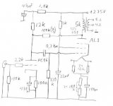
The feedback should be applied to a high impedance node. It will work better if you leave the cathode of the PC86 unbypassed.
Nope, no VR150s. Would an IRF820 and a zener string be considered blasphemy?
(There will be plenty of sand in the filament supplys, so the amp is already contaminated)
(There will be plenty of sand in the filament supplys, so the amp is already contaminated)
Fuling said:Nope, no VR150s. Would an IRF820 and a zener string be considered blasphemy?
(There will be plenty of sand in the filament supplys, so the amp is already contaminated)
Heck, no. "Sand" can be useful. Just that it's easier to kill the noise of VR tubes than that of Zener diodes.
kill the noise
I guess film caps at strategic locations can work wonders here?
I´ll have to see if there´s space for this inside the chassis, I´m not so sure about that🙂
A 1935 AL1 driven by a 1969 PC86? 14mA/V into 2.8mA/V? That's really spanning history!
> I don´t know anything about the maths behind that feedback resistor I will just start at, say, 100k and adjust until it works as intended
For small-signal analysis:
The PC86 is a voltage-to-current converter. The AL1 with a 100K resistor around it is a current-to-voltage converter. Assuming (wrongly) that the AL1 has infinite gain, the total gain (to the AL1 plate) is just Gm*100K.
If you add an unbypassed cathode resistor to the PC86, you are replacing the intrinsic Gm with a new, more-linear, but lower, Gm. "The feedback should be applied to a high impedance node." You are robbing Peter to pay Paul. Total gain available to cancel errors is still Gm. The cathode resistor will linearize the input stage; may even be necessary depending on signal level.
Since the AL1 does not have infinite voltage gain, and the PC86 has an internal plate resistance plus a DC supply resistor, gain is less.
Assuming the PC86's Gm at this (rich!) operating point is around 13mA/V, and 100 ohm unbypassed cathode resistor, and AL1 voltage gain is 12, with no feedback resistor the gain is about 270; with 100K feedback the gain is about 178. A bare 3.6dB feedback: some but not a lot. 50K feedback gives gain of 132, 6dB feedback, and so on. For "normal" hi-fi power amp sensitivity, total gain (to plate) of about 50 to 100 is called for, try 27K.
OK, for huge feedback, remove the 12K plate-feed resistor and use it for the feedback resistor. The DC conditions are (nearly) unchanged. But it will distort at very low power. When the PC86 plate tries to go high, the AL1 plate goes low, below the PC86's standing plate bias. The PC86 will overload long before the AL1. There must be a simple equality for when the feedback resistor becomes "too low", but I can't figure it out.
On the bench, reduce the 100K and watch the PC86 cathode current. (Put a 10 ohm unbypassed resistor under it.) As Rfb is reduced, the PC86 has to work harder, and will clip before the AL1 is maxed-out. When you get there, go back up in Rfb value, 1.5X to 2X higher.
> I thought about cathode feedback by putting the OPT secondary between the AL1´s cathode and GND
AL1 is only 3 watts. Assuming you take an 8 ohm tap, you have 5V RMS or 7V peak at that tap, while the AL1 needs 14V peak drive. Very little feedback. For 6dB feedback you would want a 33 ohm tap.
I am getting rather confused with this local / partial feedback thang.
Broskie used a worked example of the effect of local feedback where all current to the driver tube is applied via a resistor connected to the output tube's (300B) plate. He states that the minimum voltage drop across this resistor should be equal to the current flowing through the output tube x opt primary impedance (Ip x Rpri). The value of this resistor on the circuit's upper frequency rolloff is also discussed, but no mention is made of the impact of the value of the output tube's grid resistor (Rg) on the circuit dynamics.
However, a chapter of an old text posted by Pete Millett on the asylum (I will the post link shortly when I find it) states that the amount of feedback applied in this type of circuit is directly proportional to the ratio of Rp to Rg (where feedback is greatest when Rg >>> Rfb).
One could therefore assume that the required voltage drop across Rfb (as defined in the Broskie article) drops proportionally with the reduction in feedback due to the impact of Rg.
Neither of these texts explores the partial feedback scenario (as per the circuit diagram in this post), where plate current to the driver tube is applied via a combination of conventional plate resistor from the Ht line + Rfb from the output tube plate.
Could somebody please explain how to analyse the partial feedback scenario in the terms I have described, and in particular how to calculate the required voltage drop(s) accross Rp and Rfb to get full power output ?
Some mathematics would be great.
Correction to previous post
Sorry i meant to say
the amount of feedback applied in this type of circuit is directly proportional to the ratio of Rfb to Rg (where feedback is greatest when Rg >>> Rfb).
paulm
Sorry i meant to say
the amount of feedback applied in this type of circuit is directly proportional to the ratio of Rfb to Rg (where feedback is greatest when Rg >>> Rfb).
paulm
> the amount of feedback applied in this type of circuit is directly proportional to the ratio of Rfb to Rg (where feedback is greatest when Rg >>> Rfb).
That can't be correct, not "directly proportional", even if Rfb is also the plate resistor and the driver is a pentode. Yet I know Pete knows his stuff, so I'd like to see what he did say, in context.
The case of a triode output is a little easier because triodes won't swing the full supply voltage. Their minimum plate voltage may be no lower than the driver needs to keep from starving.
> how to calculate the required voltage drop(s) accross Rp and Rfb to get full power output?
If you already have trial values, it is easy to rough-out. Calculate the idle condition. Note the voltage on the coupling cap and replace it with a battery of the same voltage.
There are two limiting conditions:
Output tube grid high (near zero volts), output plate low (see plate curves and load-line). Calculate the new driver plate voltage. Whether the driver plate has two resistors (feed and feedback) or just one, you can calculate the current in the resistor(s). Any left over (account for direction of current) flows in the driver. What may happen is that driver current has to be less than zero, which is impossible.
The other case is output tube grid at most negative swing, output plate at most positive swing. Calculate the driver plate voltage and the current in the resistor(s). Check if the driver can pass this much current at this plate voltage without requiring the grid to go positive (which is usually forbidden).
You should include the output grid resistor and its current in your calculations, though if it is much higher resistance than the plate resistor(s) you can neglect it. The error may be 10%, but after getting a rough idea where cutoff/bottoming happens, you need to reduce driver current swing a lot to reduce THD, so the error is trivial.
For "normal" hi-fi power amp sensitivity, total gain (to plate) of about 50 to 100 is called for, try 27K.
Thats what I wanted to hear, thanks!
Would adjustable feedback be a good idea (in practice)?
I feel that it would be interesting to "tune" the amps output impedance to match my horn speakers. Both tubes are linear enough to work without NFB, IHMO.
PRR
the link I referred to in my previous post is as follows:
http://www.clarisonus.com/Archives/TubeTheory/BeamPower.pdf
As Pete said:
"If you're interested in this, read the last few pages of the document linked below (starting near the end of page 40 in acrobat, page 359 of the real document). It provides some insight, theory, and a nice practical way to figure out what the feedback does"
p42 defines feedback, n as being proportional to the ratio of Rfb and Rg (or r1 & r2) in the following equation
n = r1(r1 +r2)
regards
paulm
dang !!!! another typo.
the text is in error, the equation should be n = r1 / (r1 + r2) as per figure 33(b)
paulm
the text is in error, the equation should be n = r1 / (r1 + r2) as per figure 33(b)
paulm
> Both tubes are linear enough to work without NFB, IHMO.
I could disagree, but why be disagreeable?
> "tune" the amps output impedance to match my horn speakers.
High efficiency horns can have wide impedance swings well up into their bandwidth (not just the bass-bump and treble-rise of a low-efficiency cone). Ideally a horn's impedance is Re+Ra, where Re is the electric resistance of the coil and Ra is the acoustic resistance, hopefully mostly radiation resistance, of the horn, transformed by diaphragm area and motor-product to an electrical resistance. But it never works out that way.
Most recent horns are tuned "flat" on a zero-impedance source. Back in 1929 they were adjusted flat for an amp (and cables) with Damping about 2 or 3. A naked pentode will have Damping about 0.2 or less.
I suppose you can quick-try your horns with various source impedances, by firing-up the old transistor 50-Watt amplifier and adding a 50 or 100 ohm resistor in series with the speaker.
> BeamPower.pdf
Ah, the 6L6 Paper. Somewhat self-serving, but still darn useful.
I see the confusion: "Rg" happens to also be the grid return in this case. In Fuling's plan, the PC86 plate resistors have a similar function. However the Paper's transformer coupling does not decrease the load seen by the driver (open-grid||iron-losses) though it does increase the voltage needed from the driver. In the general plan proposed by Fuling, the driver's voltage does not increase but the impedance it sees is significantly decreased. Of course there is no free lunch: putting local feedback on the output stage always makes more work for the driver.
Hi all 
I've got two questions:
1) Please you take a look at the attached schematic. Which are the differences between plate-to-plate and plate to grid feedback? I'm thinking how to build an el84 push pull, UL connected, and I'd like to add some local feedback to improve the damping factor.
2) these kind of feedback can work with fixed bias? Any alteration in the math?
Mark
Attachments
Wait a minute, since the driver stage is supposed to have a high output impedance, wouldn´t a CCS be a better plate load than the 12k resistor? 12k is btw a bit low for the PC86, but since the B+ is only some 250V I chose 12k to get some current through the tube.
Maybe I should have a look at those MJE350´s in my junk box instead, they should be perfect for the job together with some resistors and a LED.
The increased gain and voltage swing capacity can´t be bad.
Maybe I should have a look at those MJE350´s in my junk box instead, they should be perfect for the job together with some resistors and a LED.
The increased gain and voltage swing capacity can´t be bad.
Hi all -
The amount of feedback is set by the ratio of the feeback resistor to the parallel combination of the output tube grid resistor, the driver tube plate load, and the Rp of the driver tube. Look at it like this: the feedback resistor is the top part of a voltage divider, with the other components (Rp, plate load, grid resistor) all in parallel to ground from an AC perpective.
With a triode driver, that parallel combination is usually dominated by the Rp of the driver tube. Depending on the plate load resistor it may be significant too. If you use a CCS then only Rp of the triode will matter.
I haven't tried this type of feedback with a triode driver, though I have heard a few folks who have tried it and found it worked well. With a pentode, you can get much higher gain, and more feedback, since the Rp of the pentode is very high (usually high enough to ignore).
With high Gm pentode drivers, I've used typically equal value resistors as plate load and feedback - for example, 20k from the driver plate to B+ and 20k from driver plate to output tube plate - give or take a bit.
Note that you can call this "plate-to-grid" feedback, or "plate-to-plate", since the driver plate is coupled to the output tube grid - thay're the same as far as the signal is concerned.
Just guessing here, but it does seem like you don't have enough gain with the triode driver to get enough feedback to do much good. I don't know about the output tube you're using, but most SE pentodes distort quite a bit without a fair amount of feedback.
Another thing you can try is to run the driver plate circuit from an ultralinear tap (if you have one available) from the OPT. In some cases you can use just one plate load resistor to this tap and get 40% feedback, with no other plate load resistor.
Pete
> Which are the differences between plate-to-plate and plate to grid feedback?
Plate to grid needs an extra capacitor, which complicates the frequency response calculations. Plate to plate often does not need an added cap. It also applies feedback around the grid coupling cap: for small feedback, that means you can uses a slightly smaller cap, for large feedback you have to do a full stability analysis.
Otherwise they do the same thing.
> can work with fixed bias? Any alteration in the math?
Yes. No.
> wouldn´t a CCS be a better plate load than the 12k resistor?
I hate those things: they force the triode to run at a specific current, instead of letting the triode and resistor find a natural balance. But everybody does it.
In this case, as Pete says: you have triode plate resistance and feed resistor in parallel. I estimate 2K||12K which is 1.7K, versus 2K with an ideal CSS: essentially identical.
Say you use a 27K feedback resistor (which I now think may be low for full grid swing). AL1 voltage gain is about 12. The feedback resistor looks like 27K/12= 2K2 or so. Adding or avoiding a 12K shunt (feed resistor vs. CSS) makes little difference.
I suspect the "ideal" input device has high current and low Gm. This seems counter-intuitive and may be wrong. But it reduces to a similar situation as "Slew Rate" in a BJT op-amp. To maintain large grid swing on the output, you want a large driver current and a large feedback resistor. Large FB resistor means very high overall gain (which amounts to negligible feedback) unless Gm is very low. In BJT opamps we stuff resistors under the input BJTs (or replace them with JFETs) to get large current without large Gm, so we get plenty of slew without excess gain (excess gain-bandwidth for the compensated op-amp).
- Status
- Not open for further replies.
- Home
- Amplifiers
- Tubes / Valves
- Partial feedback DHP SE amp