They called the MJW21194 a “triple diffused” type. And the data for their A1295 was the MJ15025 data (that’s right 4 MHz).
Their MJE15032/3 reflected a 50 watt 6 amp 30 MHz LAPT type (SOA that stomps ON, flat beta to 2A and still useable at 6). Having that in a TO-220 as a “super driver” would be wonderful if it could be believed. And not have QC issues, of course. If it’s not the right data (quite possible) then anything goes.
Their MJE15032/3 reflected a 50 watt 6 amp 30 MHz LAPT type (SOA that stomps ON, flat beta to 2A and still useable at 6). Having that in a TO-220 as a “super driver” would be wonderful if it could be believed. And not have QC issues, of course. If it’s not the right data (quite possible) then anything goes.

Clearly, just reading the data sheets, and other components like it.
Anything goes.
If you don't have complete data from a "manufacturer", they do not know what they are making, and you have nothing to test to. No specifications. Why would anyone buy that stuff? It's about as useful as an ECG or NTE cross reference. What is it?
Anything goes.
If you don't have complete data from a "manufacturer", they do not know what they are making, and you have nothing to test to. No specifications. Why would anyone buy that stuff? It's about as useful as an ECG or NTE cross reference. What is it?
So the original $64000 question - what would you use for outputs in this particular amp? MJL3281/1302, or are you keeping that one a trade secret?
Probably MJL21195 and 96. Then check stability if it were me. I don't have the amp in front of me to check case size.
Ft=4MHz????? EVVO manufacturing 0281/0302 with Ft=4MHz too...Their data sheets contain a boat load of errors. They’ve confused the old Sanken parts with the On MJL stuff - swapping the data and mixing “complementary” types. Trust is earned, and so far I’ve got reason to be skeptical.
Last edited:
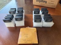
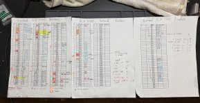
Update on my thread, I was able to source 16 pairs of new old stock 2SC3264 and 2SA1295 outputs all matched to within 1-2% of each other, special thanks to K-Amps from the DIYAudio swap meet forum, so I am back on track to restore this amp! I had to get the R channel (working channel) outputs too because I removed and tested them and they were way off, 100% variance between lowest to highest in hFE. This amp appears to be stock but not sure if it had seen abuse in its past with how badly the outputs have turned out.
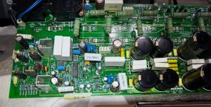
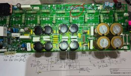
My next steps are to start checking all of the components moving backwards thru the schematic. I did find a 0.22 ohm emitter resistor reading over 1M ohms (R18), so thats one part that malfunctioned and it was connected to one of the blown 2SA1295’s. I haven’t found any shorted caps or diodes yet. There are 8 Mosfets on the driver board, 4 heatsunk, 4 each of IRF610 and IRF9610. This is my first experience with Mosfet transistors and understand they can be sensitive and difficult to handle/test without damaging them? Will need to study up on that more.
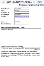
I downloaded all of the service docs I could find from the Parasound website, there is what appears to be a service bulletin to defeat the auto bias feature of the amp. This has me thinking maybe that auto bias feature malfunctioned and took out/damaged the outputs like I am seeing? Just a hunch. I am taking my time on this amp restore and want to learn as much as I can about it before launching into parts replacement. Any feedback is greatly appreciated!
My next steps are to start checking all of the components moving backwards thru the schematic. I did find a 0.22 ohm emitter resistor reading over 1M ohms (R18), so thats one part that malfunctioned and it was connected to one of the blown 2SA1295’s. I haven’t found any shorted caps or diodes yet. There are 8 Mosfets on the driver board, 4 heatsunk, 4 each of IRF610 and IRF9610. This is my first experience with Mosfet transistors and understand they can be sensitive and difficult to handle/test without damaging them? Will need to study up on that more.
I downloaded all of the service docs I could find from the Parasound website, there is what appears to be a service bulletin to defeat the auto bias feature of the amp. This has me thinking maybe that auto bias feature malfunctioned and took out/damaged the outputs like I am seeing? Just a hunch. I am taking my time on this amp restore and want to learn as much as I can about it before launching into parts replacement. Any feedback is greatly appreciated!
Attachments
Hello,
Do you have an idea why the amp failed? For me is strange that an amp with such a big number of output devices does blow.
Regards
Do you have an idea why the amp failed? For me is strange that an amp with such a big number of output devices does blow.
Regards
Any small defect in a low power stage can take out an entire bank of big, strong, beefy output transistors. The bias circuit failing, a driver, going DC, high frequency instability causing cross conduction. A small piece of wire shorting outputs, or a copper box stale failing across something that matters.
I've seen it all in nearly 50 years.
Sometimes any part just fails. Each part has an expected failure rate and sometimes they just simply fail. No other reason except it was their time.
I've seen it all in nearly 50 years.
Sometimes any part just fails. Each part has an expected failure rate and sometimes they just simply fail. No other reason except it was their time.
I figured with an amp like this around 20 years old, there could be some documented failure prone parts to replace to restore it and improve reliability? I am used to working on simpler 50-yr old stereos with lots of documentation on failure prone transistors, diodes, resistors etc since there has been a lot more time to document them and a lot more units still in operation. The only documentation I have found so far on this one is the mod on the Parasound website to defeat the auto biasing to “improve reliability”. Seems the auto biasing feature has been identified as a problem by the factory?
Attachments
I'm not sure about that. To comment I would have to examine it. Might be as simple as a pot going intermittent.
Most of those designs are reliable. Many service bulletins are about manual errors and some parts upgrades due to availability or defective manufacture (2SD234, etc). Manufacturing issues and other things do come up, but older equipment is less prone Newer stuff has no support for long term reliability (contract manufacturing).
Most of those designs are reliable. Many service bulletins are about manual errors and some parts upgrades due to availability or defective manufacture (2SD234, etc). Manufacturing issues and other things do come up, but older equipment is less prone Newer stuff has no support for long term reliability (contract manufacturing).
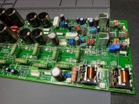
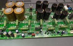
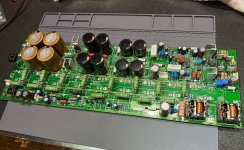
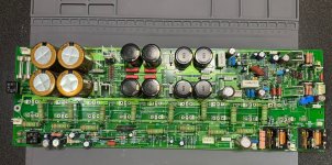
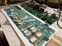
Update on my HCA-3500 repair and restore. I found the Big Sky Mod instructions in another post and decided to perform all of the mods while looking for the faulty components that caused or got damaged after the output transistor failures. The mod really cleaned up and simplified the board, it was quite satisfying removing all of the unnecessary bypass caps. I installed all of the new caps and resistors in accordance with the mod, except I subbed some films for the 1uF and less electrolytics and used Elna Silmic IIs instead of the recommended Nichicon Muse KZs.
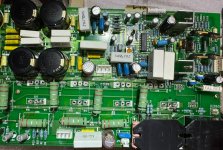
I found some faulty resistors (R11, R18 emitter resistor, R46, R139), and a few discolored resistors that looked a little damaged possibly, so replaced them (R155 and R115). I know most will say it was a waste of time and money, but I went ahead and replaced all of the diodes (1N4007s and zeners except large 33V ones) and replaced the Mosfets (4 IRF9610 and 4 IRF610). Q5 and Q36 (IRF9610 mosfets) read as a Digital transistor on my Atlas DCA55 tester, so it looks like they were damaged? Q5 was switched to an IRF9620 as per Big Sky Mod.
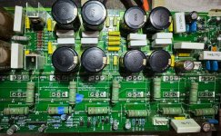
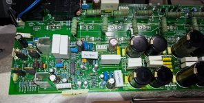
I also replaced all of the block style original films while in there, I know they didn't have to go but figured I would upgrade them along with all of the other caps I added. This has been a very complicated and time-consuming project, but I can finally see the finish line. All I have left to do is reinstall all of the driver transistors and outputs on the heat sink and I will be ready to very carefully try to fire it up on about 3 100-watt bulbs attached to my dim bulb tester and variac. I removed R94 and R140 to eliminate the dynamic bias circuit as per the Big Sky Mod. I put in new sealed trimmers, set TVR1 to near 0 ohms and TVR2 to 220 ohms. Technically TVR2 could have been replaced with a resistor but went ahead and kept it a trimmer for flexibility with bias setting if needed.
If all goes well after power up, I will do the exact same mods to the Right channel, and then the power board mods. I have attached the Big Sky Mod and a bunch of pictures of my progress. I kept a record of all of the parts I removed on a cardstock pic of the original board for record keeping. I have the relay tops to put back on, have not been able to find new relays so just going to clean the contacts up well, they appear to be in good shape. If anyone has any questions or advice, please let me know! I would love to hear everyone's thoughts on this restoration project.
I found some faulty resistors (R11, R18 emitter resistor, R46, R139), and a few discolored resistors that looked a little damaged possibly, so replaced them (R155 and R115). I know most will say it was a waste of time and money, but I went ahead and replaced all of the diodes (1N4007s and zeners except large 33V ones) and replaced the Mosfets (4 IRF9610 and 4 IRF610). Q5 and Q36 (IRF9610 mosfets) read as a Digital transistor on my Atlas DCA55 tester, so it looks like they were damaged? Q5 was switched to an IRF9620 as per Big Sky Mod.
I also replaced all of the block style original films while in there, I know they didn't have to go but figured I would upgrade them along with all of the other caps I added. This has been a very complicated and time-consuming project, but I can finally see the finish line. All I have left to do is reinstall all of the driver transistors and outputs on the heat sink and I will be ready to very carefully try to fire it up on about 3 100-watt bulbs attached to my dim bulb tester and variac. I removed R94 and R140 to eliminate the dynamic bias circuit as per the Big Sky Mod. I put in new sealed trimmers, set TVR1 to near 0 ohms and TVR2 to 220 ohms. Technically TVR2 could have been replaced with a resistor but went ahead and kept it a trimmer for flexibility with bias setting if needed.
If all goes well after power up, I will do the exact same mods to the Right channel, and then the power board mods. I have attached the Big Sky Mod and a bunch of pictures of my progress. I kept a record of all of the parts I removed on a cardstock pic of the original board for record keeping. I have the relay tops to put back on, have not been able to find new relays so just going to clean the contacts up well, they appear to be in good shape. If anyone has any questions or advice, please let me know! I would love to hear everyone's thoughts on this restoration project.
Attachments
-
 IMG_8433.JPEG588.6 KB · Views: 31
 -
 IMG_8432.JPEG484.2 KB · Views: 24
 -
 IMG_8431.JPEG578.7 KB · Views: 28
 -
 IMG_8430.JPEG570 KB · Views: 26
 -
 IMG_8413.JPEG593 KB · Views: 26
 -
 IMG_8346.JPEG619.3 KB · Views: 23
 -
 IMG_8345.JPEG605.8 KB · Views: 23
 -
 IMG_8344.JPEG587.4 KB · Views: 27
 -
 IMG_8290.JPEG474.1 KB · Views: 28
 -
Parasound HCA-3500 Audio Upgrade.pdf260.4 KB · Views: 31
-
 IMG_8434.JPEG466.4 KB · Views: 30
I read the upgrade list ...
Some things will matter a great deal. Other things do not at all. The things that matter most will normally not be visible, and make/model of capacitors don't matter as long as they are good makes. What does matter is the type of capacitor and what job it does in the circuit. But capacitors are one small part, and not all of them! Only a couple resistors matter, then you have to know what you are selecting. Selecting parts, there is the secret.
Upgrading a design or circuit is an exercise in engineering and knowledge of parts and their characteristics. With top brands, component selection occurs in the factory. That is one reason why some products are more expensive. If you can't replicate what was done in the factory for these, you may end up with reduced performance. Now, hearing it is another matter. Many folks claim they can, but reality differs - lol!
The designer of the HCA-3500, John Curl, told me that my mod was spot on. Even Richard Schram called me to say that he received excellent feedback from customers who had Big Sky Audio, LLP upgrades done on Parasound amps and preamps. Their opinions along with many satisfied customers is what matters most to me.
From what I read on the forums the HCA-3500 design was changed at the factory by adding a million bypass caps throughout the driver boards and some more on the power boards. As I understand it, removing the excess bypass caps and replacing some in accordance with the mod restores the originally intended design and greatly improves the performance of the amp. The extra bypass caps may have been a marketing ploy to make the boards look beefier or upsale by the factory to get more parts put in to increase their own bottom line. I am speculating here. There were bypass caps for bypass caps, like a Russian Doll of bypass caps!
I stuck true to the mod design except the KZ caps that I used Elna Silmic II for because I have loved their sound in my other restores and have a bunch in my stock.
I stuck true to the mod design except the KZ caps that I used Elna Silmic II for because I have loved their sound in my other restores and have a bunch in my stock.
Yeah, the use of so many bypass caps is just over the top ridiculous. Something John Curl never asked for. He submitted the design and the factory in Taiwan must have decided that they could make it even better. It is understood that paralleling caps can reduce impedance but I am of the old school where you just use a really high quality bypass cap to begin with. It does not need to be a boutique brand, an oil filled Russian WWII cap, nor a huge speaker crossover cap. What I have seen people use for upgrade caps in their audio gear is just absurd. Most of the Classic HCA series of amps have the same bypass caps layout unfortunately. I knew of this problem many years ago before it was ever talked about in forums. I owned an HCA-2200II and wanted to see about modding it and it became the test mule for my very first upgrade for Parasound. It took many months to find the right components.
Use of Silmic instead of KZ should be fine as they are just the DC rail bypasses. Again, the use of a quality cap is what really matters and I do not think using a Silmic there is going to have an effect on sound quality. I have used KZ a lot and like them. JC has referred to them as probably the next best to the old Rubycon Black Gates.
Use of Silmic instead of KZ should be fine as they are just the DC rail bypasses. Again, the use of a quality cap is what really matters and I do not think using a Silmic there is going to have an effect on sound quality. I have used KZ a lot and like them. JC has referred to them as probably the next best to the old Rubycon Black Gates.
Hi bigskyaudio,
Well, I'll believe that John said that to you.
Doesn't mean it is accurate, and my experience disagrees with it. Anyway, that topic can get religious. I'll stand by my measurements and experience with customers.
Well, I'll believe that John said that to you.
Doesn't mean it is accurate, and my experience disagrees with it. Anyway, that topic can get religious. I'll stand by my measurements and experience with customers.
Where paralleling caps makes sense is replacing one giant reservoir cap with 2, 3, or 4 smaller ones of equivalent quality. Then the ESR and ESL do go down. Not saying every design should be retrofitted, as wiring parasitics can un-do any benefit. But it’s better design practice in the first place.
Hi wg_ski,
That can be true. However, the retrofit has mechanical realities and my experience that most monkeys that do this do horrible work.
I suspect that local bypassing has a better effect when that bypass has been designed in. Nothing worse than capacitors not mechanically secure or wired improperly. I'll opt for rebuilding the capacitors the way the original was designed with similar capacitance. That's if the piece was designed well in the first place.
Advice has to be given carefully. Most people will read the "better" part and implement the idea without regard to all the other important considerations. This applies to everything or any "improvements". Then, you and I have to clean up after they have caused problems and charged someone else for "upgrades". The better techs in my area are sick to death of this, and often the damage caused can make equipment not worth repair.
One thing to keep in mind. The engineers who originally designed good equipment normally got it right with the available parts and circuit techniques. The person who roars in because they "know better" is often poorly informed. You have got to respect the original design. You have to consider what you want to change, and the actual effect it may have - if any.
Understood but paralleling was mentioned for the overuse of bypass capacitors. I do agree with the use of paralleling main filter caps.
- Home
- Amplifiers
- Solid State
- Parasound HCA-3500 with blown outputs