DEVICE: Parasound HCA-2003 circa 1998 three-channel amp
SYMPTOM: 10+ seconds after power-up with no input signal being provided (i.e., @ idle), one channel's output voltage (as read by a DVM on the outputs) slowly starts to go unstable, varying somewhat sinusoidally several millivolts positive then negative, growing in magnitude to in excess of a couple of volts. (This, of course, can cause voicecoil over excursion/damage to a connected speaker.)
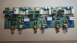
ROOT CAUSE TARGET CIRCUIT BOARD: With 100% certainty (after experiments swapping interconnects to/from other channel's boards and/or power supplies), I've isolated the culprit to be the Inputs Board. See pic. The right hand one-third of that board is the specific at fault circuit.
ROOT CAUSE TARGET CIRCUIT/COMPONENT: I simply don't know. I've A-B-C's each and every component across the three identical circuits (for the three channels) using only an ohmmeter and voltmeter. Have found all NPN transistors functioning OK, all PNP transistors functioning OK, all diodes functioning OK, all resistors very similar in resistance, pots all very similar in min and max resistance, all pot's resistance vary smoothly and similarly with rotation, all capacitors ohm'ing out very similarly.
QUESTION 1: What am I not doing that I need to do to isolate and verify what component(s) out of spec?
QUESTION 2: What additional diagnostic devices (scope, signal generator...) might be needed?
QUESTION 3: What type of component (i.e., cap, diode, transistor...) would you suspect in light of the symptoms?
SYMPTOM: 10+ seconds after power-up with no input signal being provided (i.e., @ idle), one channel's output voltage (as read by a DVM on the outputs) slowly starts to go unstable, varying somewhat sinusoidally several millivolts positive then negative, growing in magnitude to in excess of a couple of volts. (This, of course, can cause voicecoil over excursion/damage to a connected speaker.)
ROOT CAUSE TARGET CIRCUIT BOARD: With 100% certainty (after experiments swapping interconnects to/from other channel's boards and/or power supplies), I've isolated the culprit to be the Inputs Board. See pic. The right hand one-third of that board is the specific at fault circuit.
ROOT CAUSE TARGET CIRCUIT/COMPONENT: I simply don't know. I've A-B-C's each and every component across the three identical circuits (for the three channels) using only an ohmmeter and voltmeter. Have found all NPN transistors functioning OK, all PNP transistors functioning OK, all diodes functioning OK, all resistors very similar in resistance, pots all very similar in min and max resistance, all pot's resistance vary smoothly and similarly with rotation, all capacitors ohm'ing out very similarly.
QUESTION 1: What am I not doing that I need to do to isolate and verify what component(s) out of spec?
QUESTION 2: What additional diagnostic devices (scope, signal generator...) might be needed?
QUESTION 3: What type of component (i.e., cap, diode, transistor...) would you suspect in light of the symptoms?
Attachments
Welcome to the forum!
Question 1: I'd say you've already made a good start by narrowing the fault to the input portion of one channel. Am I understandlng correctly that you've exchanged front ends with power output sections and the fault lies consistently in the right most circuit-board section?
I recommend posting a schematic/service manual of your amp. That will make it much easier to converse with members.
Question 2: A scope is probably the most useful tool, and then a generator. I believe many members use cellphone apps for signal generation.
Question 3: Electrolytic caps and transistors are most likely culprits, though others may differ.
A schematic is best place to start, IMO.
Good luck!
This would be the first thing I pull and test - the capacitor may not be bad, but certainly doesn't look good. as BSST mentioned, I would start with some cold spray on the transistors and see if you can replicate by cooling one of them and narrow the search even more. Then you will likely have to pull and test some parts to finally repair it.

Very good catch. I also saw that and replaced it. See (new) pic showing replacement cap in place. (What's under/around it is adhesive, not leaked electrolyte.) However, replacing it did nothing to the symptoms. I intend to change the neighboring cap, and the only two other electrolytic caps on that (section) of the board. Per the schemati, they are C35, C123, C40, and C41.This would be the first thing I pull and test - the capacitor may not be bad, but certainly doesn't look good. as BSST mentioned, I would start with some cold spray on the transistors and see if you can replicate by cooling one of them and narrow the search even more. Then you will likely have to pull and test some parts to finally repair it.
View attachment 1120344
Attachments
If it was me and I didn't have a scope, I would start with either compressed air can, turned upside down (cheap man's cold spray) and start with Q25-Q31 to see if you can replicate or see it get worse.
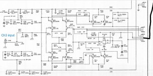
Otherwise, start checking the B-C-E junctions for voltage drop with a DMM and see if you have one of more that don't match the others. Then if that turns up nothing, do the same for the TO-126 on the heatsinks. If you still don't have a smoking gun, I would begin pulling the transistors out of the board one-by-one and test them with a transistor tester. Starting with TO-92s - Q25, Q27, Q31 and Q34, then move to the JFETs, Q26, Q28, Q29, Q30. My guess is that one of those is leaky sending DC and the leakage gets worse as it heats up.
Otherwise, start checking the B-C-E junctions for voltage drop with a DMM and see if you have one of more that don't match the others. Then if that turns up nothing, do the same for the TO-126 on the heatsinks. If you still don't have a smoking gun, I would begin pulling the transistors out of the board one-by-one and test them with a transistor tester. Starting with TO-92s - Q25, Q27, Q31 and Q34, then move to the JFETs, Q26, Q28, Q29, Q30. My guess is that one of those is leaky sending DC and the leakage gets worse as it heats up.
Everything looks similar, measures similar, but the right hand side acts differently... first thought: mechanical?
Apart from above recommandations, check for suspicious solderings, broken tracks, discontinuities especially near fixing points/posts, and the connectors too! One loose pin within the connector, even if it appears ok, can spoil all the fun.
Apart from above recommandations, check for suspicious solderings, broken tracks, discontinuities especially near fixing points/posts, and the connectors too! One loose pin within the connector, even if it appears ok, can spoil all the fun.
This amp features DC servo nulling of output. Because you describe slow (oscillatory?) behavior, I suspect the servo amp.
Would you monitor U3 pin 6 with your voltmeter and see if it mimics behavior of the amp output? If it does, I will have a couple further tests to suggest to identify the problem.
Would you monitor U3 pin 6 with your voltmeter and see if it mimics behavior of the amp output? If it does, I will have a couple further tests to suggest to identify the problem.

Good news - progress. I finally pulled this beast out of the rack and have the following observations.If it was me and I didn't have a scope, I would start with either compressed air can, turned upside down (cheap man's cold spray) and start with Q25-Q31 to see if you can replicate or see it get worse.
Otherwise, start checking the B-C-E junctions for voltage drop with a DMM and see if you have one of more that don't match the others. Then if that turns up nothing, do the same for the TO-126 on the heatsinks. If you still don't have a smoking gun, I would begin pulling the transistors out of the board one-by-one and test them with a transistor tester. Starting with TO-92s - Q25, Q27, Q31 and Q34, then move to the JFETs, Q26, Q28, Q29, Q30. My guess is that one of those is leaky sending DC and the leakage gets worse as it heats up.
1) At room temp, upon numerous resistance and diode checks across the target TO-92s and JFETS comparing all three channels components, I could not discern a single difference.
2) At operating temp, when the original symptom would occur (somewhat slowly cycling positive then negative offset reaching 2+ volts in each direction), the root cause would heal when blown with cool air. The most likely culprit is the Q27 Q32 pair. Notice in the (new) close-up pic (attached) the close promixity of these two. So the root cause of failure of thermal fatigue?
3) A new symptom would be exhibited after soem power up shot down events... a static -1.46 [Vdc} offset with "THX Level" pot on rear of amp @ its min level, -1.62 [Vdc} offset with "THX Level" pot @ its max level. Efforts to cool the suspect transistors would not lead to any healing of this symptom.
Will post again when parts arrive and I begin pulling these TO-92s, checking them with a component tester, and hopefully replacing the root cause component(s).
Attachments
![DSC_6755[1].JPG](/community/data/attachments/1040/1040237-d83897f6c4ce7555e278dfa8224538d0.jpg?hash=2DiX9sTOdV)
Is the "THX Level" pot level control R79?
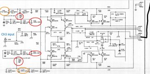
The root problem may well be error in the input pairs (Q26-Q28 and Q29-Q30), but I recommend testing the DC servo as a first step. It's possible the servo itself is oscillating. Alternately, if it is operating correctly, it will try to automatically set to output voltage to 0V; in consequence, it will tend to suppress/obscure the drift errors that are the real underling problem. You'll observe erratic voltage on U3 pin 6 as it attempts to correct offset errors to 0V.
To test servo, install temporary shorts across C148 and C149. If opamp U3 is healthy, its output voltage on pin 6 will be within a few mV of 0V. Now you can test output offset error without incurring corrective intervention from the DC servo. (Leave the caps shorted until the problem is resolved, then remove to restore servo nulling.) Now you may find output error is even larger and continues to be "drifty" and erratic; this suggests drift in the input transistors. But if the output error remains relatively stable (even though large) at the amp output, this points back toward servo oscillation. Suspect C148 or C149, or connections to them. Maybe the opamp, though less likely.
Good luck!
I've received ten each of 970 and 2240 transistors for the input stage. I've recorded each device's hfe but am confused in the literature on what is ideally matched with what. I assume each pair (i.e., one npn and one complimentary pnp) should be selected to be as close as possible to each other. I also assume that it's no significant consequence if, for example, one pair is matched at values close to X, another pair matched at values close to Y, and the third pair matched at values cloae to Z. Q1: Correct?
I intend to replace the most suspect single complimentary pair, then test to see if the symptom (oscillation/instability discribed earlier) is gone. Q2: If the symptom is indeed resolved, should any efforts be made to remove the remaining two pairs, record their respective hfe values, then eithher reinstall them or insert new components with hfe values close (relatively speaking) to the initially replaced pair?
Lastly, while a newbie to electronic amp topology, I was a controls engineer (now retired) and fully appreciate the suggestion to examine the servo op-amp. I intend to conduct any/all such checks BEFORE proceeding with any 970/2440 pair(s) replacement. Q3: Comments?
Much appreciated !!
Does the problem channel "work" and make music when a speaker is connected? Does the DC offset behave differently with/without a speaker/dummy-load connected? Does the speaker protection relay engage when the DC offset exceeds +/-1.4V? Before diving into parts swapping, perhaps consider the possibility of the amp going into instability? Best to take a look with an oscilloscope, if not available, there are indirect ways of testing. e.g. 1/ measure the offset at the output with an R-C low-pass filter at the test leads, 10kohm-0.1uf, to cut out high-frequencies, and see if the reading is any different. 2/ temporality parallel a 100pF cap over C130 and see if it changes the DC offset. 3/ replace the capacitors C143 and C157, these are part of the output Zobel network that can be critical for stability of the particular feedback/compensation topology used in this amp. Just a thought.
Q1 from nattawa: Does the problem channel "work" and make music when a speaker is connected?
A: No. As stated in the opening post: "10+ seconds after power-up with no input signal being provided (i.e., @ idle), one channel's output voltage (as read by a DVM on the outputs) slowly starts to go unstable, varying somewhat sinusoidally several millivolts positive then negative, growing in magnitude to in excess of a couple of volts." (This, of course, can cause voicecoil over excursion/damage to a connected speaker.) So with a speaker (woofer of a B&W 801-II monitor) connected, the DC present in the signal will cause the cone to move from one maximum excursion to the other maximum excursion. To avoid damage, no further experimentation was conducted.
Q2 from nattawa: Does the DC offset behave differently with/without a speaker/dummy-load connected?
A: See answer to Q1 above.
With regard to suggestions relative to C130, then both C143 and C157, none of these caps are even in the Channel 3 Input Stage topology. So I see no connection they may have to the root cause. Note: "ROOT CAUSE TARGET CIRCUIT BOARD: With 100% certainty (after experiments swapping interconnects to/from other channel's boards and/or power supplies), I've isolated the culprit to be the Inputs Board. See pic. The right hand one-third of that board is the specific at fault circuit."
Thanks for the ideas/input.
Correction: I see C130 on the opamp noninverting input. So I may test with a bypass cap as suggested. Q: If the instability symptom changes, what would then be the conclusion?
I was assuming an expendable speaker, like one from an auto junkyard or from a garage sale, would be used for troubleshooting a power amp. A dummy load such as an 8-10 ohm high power resistor in place of a speaker also works.
C143 and C157 are at the back end of the amp but they (together with the resistors in series with them) may have an effect on the stability margins of the global feedback loop that they themselves are part of. However since you have exhausted the possibilities by rotating/swapping channels during testing, perhaps the loop instability could be ruled out.
C143 and C157 are at the back end of the amp but they (together with the resistors in series with them) may have an effect on the stability margins of the global feedback loop that they themselves are part of. However since you have exhausted the possibilities by rotating/swapping channels during testing, perhaps the loop instability could be ruled out.
UPDATE:
Have replaced a total of four TO-92s. Specifically, two A970 (Q27 and Q31) and two C2240 (Q25 and Q34). I choose the most closely matched pair(s) for hFE (A970s @ 340 and 336, C2240 @ 355 and 356).
Symptom remains, though somewhat different Vdc values. The earlier reported (unstable) symptom exhibited a slowly, somewhat sinusoidal, positive going then negative going offset. Also, blowing cool air across those four TO-92s would have significant impact on behavior. The current symptom varies slowly and is most often a negative value like -1.62 Vdc. Blowing cool air there still can affect output but not as significantly.
So unless there are words of wisdom out there to share, I'll replace the servo opamp AD711JN.
The -1.4V voltage you observe is a reasonable magnitude, but it shouldn't be oscillatory. I still recommend shorts across C148 and C149 as diagnostic simplification. If you see about 0V at opamp output, that's suggestive that opamp is ok. Test amp without servo correction. There may be DC present at output, but it should be relatively stable; might show some modest sensitivity to temperature. Once the amp is well behaved, remove short across C149; there should be modest correction of output error, but no oscillation. The filter at C149 has a 1 second time constant--- you'll probably be able to sense it's "slow." Then remove short across C148; output error should drive to only a few mV. The servo should be able to null initial amp offset error of more than 2V.
Last edited:
Looks like there's a bit of corrosion on the PCB. This could be causing leakage issues if it's a multi-layer PCB.
Did you check R69? High value resistors often go higher in value with age, sometimes even O/C. Servo caps might also be worth checking.
Did you check R69? High value resistors often go higher in value with age, sometimes even O/C. Servo caps might also be worth checking.
Forgot to mention you should also monitor the +/-12V servo supply to see how that compares between the 2 channels.
To all who've contributed here in my effort to resolve the DC offset issue, I have an update AND a request.
UPDATE:
I just replaced the servo amp (AD711) and the symptom persists. With the amp off all three channels exhibit 0.000 to -0.002 Vdc. As is always the case, about four seconds after power-up Stand-by clears and the main relay powers the amp. Then the output on Channel 3 jumps to -3.23 then begins to lessen in value until settling at - 1.46 in ten seconds (after it initially jumped up).
If I blow ambient air at the target area the offset will reach -4.6 Vdc. When not longer blowing ambient air there it settles back to the aformentioned -1.46 Vdc.
In one instance of blowing ambient air at the target area it reached -5.6 at which time I believe the Channel 3 output protection relay tripped (open). At that moment the offset went to about zero. Then, assuming after the relay closed it repeated the same symptom as stated above (i.e., jumped to -3.2 Vdc then in ten seconds settled back to -1.46 Vdc).
So to date I've replaced:
a) four electrolytic caps, specifically C35, C123, C40, and C41
b) four TO-92s, specifically, two A970 (Q27 and Q31) and two C2240 (Q25 and Q34)
b) the servo op-amp AD711
REQUEST:
Suggest next steps. Such as:
a) Replace C148 and/or C149.
b) Replace four remaining TO92s, Q26 Q28 Q29 and Q30.
c) Conduct a test (suggested earlier by BSST).
d) tbd
- Home
- Amplifiers
- Solid State
- Parasound Amp Unstable Channel Output - Seeking Troubleshooting Advice