1
------------------------------------------------------------
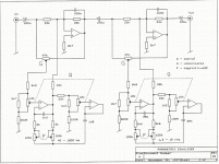
2 * PI * sqrt ( (r10+r12) * c4 * (r11+r12) * c5)
for r12=0 I calulated 36Hz
for r12=100k I calulated 1250Hz
Where did you find this circuit
------------------------------------------------------------
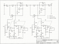
2 * PI * sqrt ( (r10+r12) * c4 * (r11+r12) * c5)
for r12=0 I calulated 36Hz
for r12=100k I calulated 1250Hz
Where did you find this circuit
Thanks so much, that really helps me out. I got the schematic from a website I can't seem to find anymore. It's originally from a piece of Studio gear, I'm not too sure which one. All I know it that on the website it said the design was highly regard.
It's nice to see some people on the right track. This is a generic circuit using op-amps. Other successful parametric designs are very similar. By the time "they" get their digital circuits adjusted the CD is over. A circuit like this, properly built and adjusted to do it's job, built with 25 year old XR4136 bipolar op-amps as compared to a newer one built with the latest National j-fet op-amps, will be indiscernable to a critical listener on a good system. In other words, correct parametric equalization is one of the most important factors of a great sound system. It doesn't matter what kind of religious annointing you have bestowed upon your transistors, as long as they are operating where they are supposed to be, and constructed on a good backbone. Anyone want to have a tug of war? (Your power amp and mine, output connected to output, any way you like with any load, and any input signal you want. The first smoker is the loser.) Back to Tom Waits. Don't go into that Barn.
I downloaded the schematic for the parametric EQ. I have been simulating it using Pspice. It is very nice. I am still a little unsure how it all works, and that is why I am writing.
Does anyone know the calculations for "Q" ? The present circuit values provide a very low Q, even with the pot all the way up. I would like to increase this even further. Any ideas?
What I like about the circuit is that the Q setting affects the overall output amplitude very little. This circuit offers a good independece of Gain, Frequency, and Q control.
I would really like the formula for Q if anyone knows how to derive it.
Thanks,
Joel
Center Freq./(high -3dB down point minus low -3dB down point)=Q. What's Pspice?giggles said:I downloaded the schematic for the parametric EQ. I have been simulating it using Pspice.
I would really like the formula for Q if anyone knows how to derive it.
Feedback eliminator
Could this be used on a line input. Require a budget parametric eq for a vocal microphone, thought I'd DIY a unit. If you could email all the details, be great!
Thanks.
Could this be used on a line input. Require a budget parametric eq for a vocal microphone, thought I'd DIY a unit. If you could email all the details, be great!
Thanks.
- Status
- Not open for further replies.
- Home
- Design & Build
- Parts
- Parametric Schematic


