Here's all you need:
http://www.reed-electronics.com/ednmag/contents/images/330071.pdf
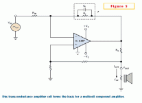
If the math scares you, fig 8 says it all - although it has one glaring error, can you spot it?
Jan Didden
http://www.reed-electronics.com/ednmag/contents/images/330071.pdf
If the math scares you, fig 8 says it all - although it has one glaring error, can you spot it?
Jan Didden
If we only take missing connections (dots) into account: FOUR errors, or are there fundamental mistakes?
Steven
Steven
Sorry Mikett,
The moment I was writing, your post was not yet on my screen; only after submitting your post popped in between. Maybe some caching issue, or I should refresh more often.
Although I have had this before: I answered on a thread and my answer was there already in the thread for more than an hour (if I remember correctly), even after some refreshing, and suddenly other posts with an earlier time stamp came in between, making my post look silly because the reference was a number of posts earlier. I don't know how this can happen.
😕
Steven
Steven said:If we only take missing connections (dots) into account: FOUR errors, or are there fundamental mistakes?
Steven
I see (or rather, don't see) 4 missing dots.
Jan Didden
Steven said:Sorry Mikett,
The moment I was writing, your post was not yet on my screen; only after submitting your post popped in between. Maybe some caching issue, or I should refresh more often.
Although I have had this before: I answered on a thread and my answer was there already in the thread for more than an hour (if I remember correctly), even after some refreshing, and suddenly other posts with an earlier time stamp came in between, making my post look silly because the reference was a number of posts earlier. I don't know how this can happen.
😕
Steven
This happens because you are still under moderation.
Within a few time you'll become a "regular" user of the forum, and no longer suffer for moderation delay.
Cheers
Andrea
Hope I'm not gotting to embrass myself, but aren't there 8 dots missing and the feedback resistors are too small.
Errors? This is nothing, remember the guy's a mathematician. I'd hate to see his woodworking projects.
analog_sa said:So the right way is to do it inverted 🙂
I think the significance of this circuit is that it makes the individual circuits transconductance amps by feeding the information on the output current back to the non-inverting input. In this way, there is almost perfect sharing of the current among the chips, even with very low sense resistors. This limits the waste of power.
This circuit is known in the trade as a Howland Current Pump, IIANM.
Jan Didden
Jan
The sharing resistors appear to be of similar value to the normal paralleling topology. Is it really a question of better efficiency or is a transconductance amp simply better suited to drive a speaker load? Hmm, maybe i should add two resistors to my GC and give it a listen.
Anyway, thanks for the link - it is certainly interesting
Well, I haven't had time to look at it in detail, but as far as I know, a transconductance amp delivers a current in response to an input voltage, it's gain is xx amps/volt. In parallelling these chips, this would inherently be an advantage because it automagically insures almost perfect sharing. I also noted that he assumes 2Ohm load. The author clearly was interested to optimize the output power from a specific number of chips, not min THD or something like that.
Does anybody know what output impedance this configuration has? Is it voltage or current drive?
Jan Didden
Does anybody know what output impedance this configuration has? Is it voltage or current drive?
Jan Didden
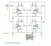
Current Sharing article in EDN Magazine
in the mailbox arrives the most recent issue with a very good article on paralleling LM3886's -- well worth viewing, you will find the reason for the feedback capacitor in the article:
http://www.reed-electronics.com/edn...stt=000&articleid=CA330071&pubdate=10/30/2003
in the mailbox arrives the most recent issue with a very good article on paralleling LM3886's -- well worth viewing, you will find the reason for the feedback capacitor in the article:
http://www.reed-electronics.com/edn...stt=000&articleid=CA330071&pubdate=10/30/2003
Attachments
- Status
- Not open for further replies.
- Home
- Amplifiers
- Solid State
- Paralleling LM3886's-the right way