Quad produced mono kits for the 405 which paralleled the 2 channels to drive low Z loads, details can be found here,
https://www.dadaelectronics.eu/uplo...Documents/Quad-405-Monoblock-Instructions.pdf
I found it worked very well, it also worked well with the 306s
Stuart
https://www.dadaelectronics.eu/uplo...Documents/Quad-405-Monoblock-Instructions.pdf
I found it worked very well, it also worked well with the 306s
Stuart
Could I just connect the psu's in parallel? Jim Stuart of Meridian answered a question years ago on a forum regarding the 'lean' nature of the Meridian 105 mono. He said what they need is a bigger transformer. Would this satisfy that need? Would this double the va rating? Since the psu and amp are in separate chassis, it would be easy to piggy-back them.
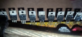
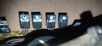
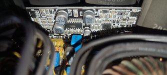
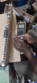
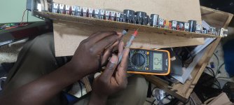
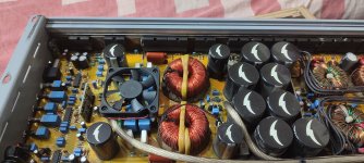
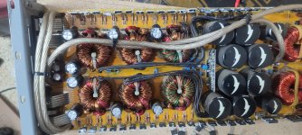
hello all this too is a high power class d using +/-125 vlts and its paralled in the outputs , also i cannot see any output resistor used before output. (i think they are the four white droppers resistor next to the output inductor)
the amplifier is stable up to 1ohm
the amplifier is stable up to 1ohm
Attachments
-
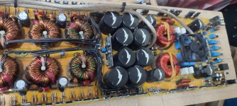
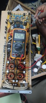
 IMG_202410 12volts power supply boost stage.jpg243.5 KB · Views: 53
 -
 IMG_20241010_185153.jpg362.1 KB · Views: 51
 -
 IMG_20241010_184425.jpg394.1 KB · Views: 52
 -
 IMG_20241010_184421.jpg402 KB · Views: 56
 -
 IMG_20241010_1519 rectifier diodes.jpg201.3 KB · Views: 65
 -
 IMG_20241010_1519 drive board for output fets .jpg247.8 KB · Views: 54
 -
 IMG_20241010_183voltage .jpg393.9 KB · Views: 51
 -
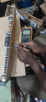 IMG_20241010_183 voltage positive.jpg313.2 KB · Views: 58
 -
 IMG_20241010_183 voltage negative.jpg338.1 KB · Views: 59
 -
 IMG_20241010_183 voltage full rail.jpg334.9 KB · Views: 55
 -
 IMG_20241010_165 output fets used.jpg206.7 KB · Views: 58
 -
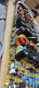
 IMG_20241010_023 amplifier section.jpg389.1 KB · Views: 56
 -
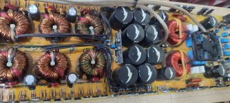
 IMG_20241010 dc 12v booster section.jpg435.9 KB · Views: 63
Paralleled output transistors is not the same as paralleling entire amplifiers. Most big amps use paralleled transistors.
The reason you usually want lower impedance capability (in PA equipment) is to run multiple speakers/drivers. If you are going to use two channels anyway then just run some of one amplifier and some off another. If you’re trying to run a 4 ohm 2x18 and have two amps only capable of 8 ohm, just rewire the darn speakon plate and run two cables. Go to sell it later, just put it back.
The reason you usually want lower impedance capability (in PA equipment) is to run multiple speakers/drivers. If you are going to use two channels anyway then just run some of one amplifier and some off another. If you’re trying to run a 4 ohm 2x18 and have two amps only capable of 8 ohm, just rewire the darn speakon plate and run two cables. Go to sell it later, just put it back.

thanks wg_ski for the reply .do you have a schematic diagram of paralleled class d amp or paralleled ac smps ? kindly share here if you do
"The Bridge" is just a polarity inverter using line level input transformers to feed stereo amplifiers to make them function as a bridged mono amp.Hi. I'm wondering if there's such a thing as a universal paralleling 'box' you can plug two identical mono amps into to lower impedance capability. G.A.S. aka James Bongiorno did produce a bridging box called "The Bridge" for bridging their amps which was a universal circuit. TIA
A "universal paralleling box" to combine the output of two identical mono amps could be done with a pair of speaker level audio transformers.
The cost of high-quality full-range 100 watt audio transformers would exceed the cost of new power amplifiers with more power than your circa 1978 100 watt @8 ohm Boothroyd Stuart Meridian 105 amps.
What speaker loads do you want to drive with your four amps?
In addition, when paralleling transistors in an amp circuit, the array is self balanced, since if one transistor starts to conduct more, it's Vbe or Vgs will drop and make it conduct less. One more thing, the feedback is usually taken after all the transistors joined, so any drop on the Rc resistors will be compensated.Paralleled output transistors is not the same as paralleling entire amplifiers. Most big amps use paralleled transistors.
The reason you usually want lower impedance capability (in PA equipment) is to run multiple speakers/drivers. If you are going to use two channels anyway then just run some of one amplifier and some off another. If you’re trying to run a 4 ohm 2x18 and have two amps only capable of 8 ohm, just rewire the darn speakon plate and run two cables. Go to sell it later, just put it back.
When paralleling amplifiers out from their boxes they "compete" to set the voltage on the speaker since solid state amps are essencially a voltage source and there is no feedback to compensate the serie resistor voltage drop. Damping factor will be poorer.
A solid-state amplifier (Class A, AB, D etc) is built to exactly reproduce the waveform of the input signal. With a larger amplitude but with all others the same. The output impedance is as low as possible, ideally being zero. This something else as minimum resistance to be connected, that might be 8, 4 or 2 ohms or something else. So the amplifier is designed to act as a voltage source.
According to network theory you cannot connect voltage sources in parallel. So the simple answer is no, you cannot connect these amplifiers in parallel to increase the current rating. Not.
This is slightly different for tube amplifiers which final stage is not a voltage source approaching an ideal voltage source. Since the amplifier has a finite output conductivity (R > 0) you could parallel tube output stages. How to do this properly is by no means trivial and it even might not be practical. But theoretically it can be done.
RF class C amplifiers with a defined output impedance are commonly paralleled.
Class C (or any other class) of RF power amplifier are power combined, which is not the same as paralleling. The phase across the power combining device is usually some multiple of 1/4 wavelength. And they often have balancing resistors to keep them from fighting one another.
Sorry to disagree but I was not talking about Class C "power combined". I was talking about paralleling two complete Class C transmitters. Behind the tank circuit, behind the harmonics filter. And no resistors or anything. The output of these class C amplifiers are 50 (or something else) ohms by design and hence they could be paralleled.Class C (or any other class) of RF power amplifier are power combined, which is not the same as paralleling. The phase across the power combining device is usually some multiple of 1/4 wavelength. And they often have balancing resistors to keep them from fighting one another.
This particular type I worked with (Philips 250 kW short wave) had a pick-up coil in at the antenna so the phases of the two transmitters could be synchronised. I know it was also done with LW or MW transmitters. With higher frequencies like FM coupling usually is performed using 1/4 lambda couplers that is correct.
Simple question, simple answerHi. I'm wondering if there's such a thing as a universal paralleling 'box' you can plug two identical mono amps into to lower impedance capability.
There is no universal paralleling box.
Now everyone can resume arguing over slightly related, but mostly off topic subjects.
The max output voltage would still be the same. So no extra overhead.
Would only be useful for more current. Such as horrible 2 or 1 ohm loads.
Which are easy to avoid.
For more Voltage you have to float the load. Otherwise known as bridging
Or just buy a amp with more voltage output.
Last edited:
Great timing! I just logged in. Can you comment on my post #22? In terms of parallel redundant operation.
The max voltage swing is still the same before clipping.
Your just adding more current. Parallel
So it is only useful if the impedance was very low.
That is the problem with years of solid state marketing from the 70's
Which claim " More Power" with low impedance.
Your not getting more power, your using more power.
The amp still clips at its voltage limit. It just needs more current to drive
low impedance loads.
So driving the same old 8 ohm load.
If you wanted it less likely to hit clipping.
You need more voltage. Hence the power rating at the same impedance.
The difference between 100 watts 8 ohms and 200 watts 8 ohms
is more voltage. And of course enough current to support that higher voltage.
= plain jane ohms law
You could parallel PSU's at the point of the capacitors. If the PSU's are more or less equal. I don't know the type you are referring to so that might be different. But in principle, yes.
There are some considerations like connections and ground loops. If the power supply you are adding has a considerably lower voltage but the capacitors are still rated for the first voltage it does do no harm but the use is limited. If the current rating of the supply you are adding is different, you are still adding so that is fine.
There are some considerations like connections and ground loops. If the power supply you are adding has a considerably lower voltage but the capacitors are still rated for the first voltage it does do no harm but the use is limited. If the current rating of the supply you are adding is different, you are still adding so that is fine.
Last edited:
I dont know where it is leading.
Again to get more voltage swing from amps with a voltage limit.
You have to float the load, Use 2 amps and reverse the polarity of one amplifier.
Aka = Bridge
Those tradeoffs have already been mentioned.
To magically get that extra voltage swing, you actually need more current.
No big surprise, luckily we have 2 amps now with 2 transformers.
All good.
As mentioned the load is floating, so now a 8 ohm load looks like 4 ohms to each amp.
So your using even more current. But you are getting more voltage swing.
It just tends to stress the amps and make more heat.
The amps didnt magically get more transistors on the outputs.
So you just run the risk of heating up components.
So as normal if a amplifier min load is 4 ohms. Then if you bridge 2 amps for more voltage swing.
Then your actual bridge load or floating load minimum is now only 8 ohms not 4 ohms.
No free lunch. But yes more voltage before clipping.
Far as redundant operation, yes agree. But you dont do it with 2 feedback loops. Or 2 amps parallel
You just make 1 amp 1 feedback loop with more voltage, more current and more transistors.
So yes in the spirit of Diy making bigger and better amps = sure
Or for plug n play you just buy higher powered amps.
Last edited:
The issue with the 105s was "slam". They are a bit lean on bottom end transients. Very quick but lean. I have 3 pairs so It would be interesting to see if this can be overcome. The transformers are only 150va. Otherwise the performance is world class imo. I love good vintage gear, breaking through.
- Home
- Live Sound
- PA Systems
- Paralleling amplifiers