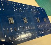
A while back the illustrious Jan Didden published an amp design using multiple paralleled AD815s. The packages he used were those suitable for bolting to heatsinks whereas I have several tubes of the SMT version which gets its cooling via its mounting tabs to the PCB. So I figured to try out mounting several on a bare copper double sided PCB. The top side is the +ve rail as that's the potential for the heatsinking tabs. Rail decoupling is supplied by the edge-mounted 'lytics :

The above are a couple of early prototypes - on the lower one (stereo) I had the chips a bit too close together so they ran rather too hot. The second was just a single channel with greater chip spacing but at higher supplies still ran rather too warm. It took me a while but eventually I realized that much of the dissipation wasn't as a result of the load current, rather it arose due to the varying offset voltage of the AD815s. Put another way - there was too much cross-current between paralleled amps at DC. At first I thought that having a trimmer on each would fix that but then decided rather to couple the amps together with caps so the DC level became mostly immaterial.
Just this week I got PCBs back for a stacked version of this which gives nice flexibility of how many chips to use in different applications. For example, a mini desktop amp might only need 3 stacked boards per channel, giving 1.5A peak output current.

The general idea is to pile them up like this (subject to experiments to see how hot they get!) :

The above are a couple of early prototypes - on the lower one (stereo) I had the chips a bit too close together so they ran rather too hot. The second was just a single channel with greater chip spacing but at higher supplies still ran rather too warm. It took me a while but eventually I realized that much of the dissipation wasn't as a result of the load current, rather it arose due to the varying offset voltage of the AD815s. Put another way - there was too much cross-current between paralleled amps at DC. At first I thought that having a trimmer on each would fix that but then decided rather to couple the amps together with caps so the DC level became mostly immaterial.
Just this week I got PCBs back for a stacked version of this which gives nice flexibility of how many chips to use in different applications. For example, a mini desktop amp might only need 3 stacked boards per channel, giving 1.5A peak output current.
The general idea is to pile them up like this (subject to experiments to see how hot they get!) :

Load sharing (series) resistors would also function OK to mitigate inter-IC currents. Cheaper than good caps and likely more reliable too.
As you apparently have a stack of SMD AD815, I just realized by reading your thread that I have a stash of the SIP15 version.
How do they perform? Worth the effort? BTW the Molex KK 0.1 are usable up to 3A. For more current screw type connectors are preferred usually.
As you apparently have a stack of SMD AD815, I just realized by reading your thread that I have a stash of the SIP15 version.
How do they perform? Worth the effort? BTW the Molex KK 0.1 are usable up to 3A. For more current screw type connectors are preferred usually.
Last edited:
Load sharing resistors I've already included, I think they're essential. On the top pic, those are the 1Rs R10 and R11. So far I think yes, worth the effort but I've only listened to the stack-of-3 version so far, need to build up more PCBs. The output KK2510 connectors only have to deal with the max output current of one AD815 which is 0.5A, so plenty in hand there.
Are you going to put your stash of '-AYS' to good use?
@ClaudeG - cheers!
Are you going to put your stash of '-AYS' to good use?
@ClaudeG - cheers!
Maybe. I suffer from DIYers-disease of having too much parts and too wide view. Also satisfied with SMSL AO200 mkII that came for a short visit but stayed.
Always interested in your projects Richard and was hoping for another of your amp developments. Watching with interest.
What may the power output be given x_n of chips.?
What may the power output be given x_n of chips.?
Hi Jim - the maximum power output - where the number of AD815s isn't a constraint - is set by the maximum power supply volts which is 36V. Assuming some loss in the output stage that gives about 32V peak or 22VRMS which corresponds to 64W into 8R. In theory that would need 10 chips to cope with the current. Thermals not considered - the chips might get too hot just from the quiescent current with a 36V rail. JP's SIP15 packages though would certainly be up for this as they're designed for mounting to a real heatsink.
That brings back memories! Richard you could probably get away with two chips on the board area you used (opposite sides of the PCB), especially if you put one of those glue-on small heatsinks on each chip. Cuts the required number of boards in half.
Those SIP packages are rare - I got a bunch from Scott Wurcer at the time. Scott designed the chip.
BTW, on the current share issue, I mentioned:
"You will note that I use a lot of 2k resistors, even two in // when I needed 1k. The reason is that I want those resistors to be very much equal in value, and I selected 0.1% tolerance units. If they are not equal the gain of the individual stages may not track well which might lead to all kinds of equalisation currents from one opamp into the other, and that's lost power and wasted heat."
Even when you combine the outputs AC-coupled, there still might be equalisation currents for signal frequencies.
Jan
Last edited:
Jan - thanks for your remarks, I was dimly aware AD815 was one of Scott's. I'm already using 0.1% resistors for setting the gain. The way to check for cross-currents is by monitoring the supply current with no load attached. Then apply a low level signal, say just 1% of full output swing. Slowly ramp up the amplitude while watching the supply current - if the quiescent starts to rise with increasing signal then you've got cross-current issues.
There were later designs for ADSL drivers after AD815 but all seem to be compromised on noise in comparison with the original. AD8016 being a case in point - the lower end of the audio band shows a rising noise trend. Even THS6012 which is the more fully specd/tested version of TPA6120 has inferior LF noise to AD815 (yet its claimed to be an upgrade of Scott's chip).
Left AD815, right THS6012 :
There are some SIP15 AYS on AliExpress. 5 for £15. Is it a silly question to ask if the AD815AYS got faked?!
I don't recall having seen any of those examples at least. Never say never and all that, but industry demand for DSL line drivers is probably not great, and audiophiles building preamps here and there is probably not a great revenue source either.
I would be a bit more concerned about getting pulls from used equipment or stuff that has been stored "inappropriately", but if the ICs you receive are look genuine and in good condition I would not personally hesitate to use them.
I would be a bit more concerned about getting pulls from used equipment or stuff that has been stored "inappropriately", but if the ICs you receive are look genuine and in good condition I would not personally hesitate to use them.
Jim - I think they're more likely to be pulls than fakes, although I don't have direct experience of AD815AYS. Does that price include 'free' shipping? If not they're a bit expensive, price on Taobao is about half that.
When ordering there one can expect literally everything. I recall Röntgen pictures of pulled ICs that had severe ESD damage. Also the woks cooking SMD parts of PCBs 🙂 The techniques used to disguise parts that are pulls are quite good.
For me unknown sources don't work looking at the effort to create something and exactly the main parts of the design being an insecurity. I just want new/original/unused/ESD safe treated parts for cheap 😀
For me unknown sources don't work looking at the effort to create something and exactly the main parts of the design being an insecurity. I just want new/original/unused/ESD safe treated parts for cheap 😀
Last edited:
That looks interesting, may we see the other side too? I'm curious what those AD815s are part of.
Thank you! So is this a balanced headphone application of AD815? Four chips doesn't seem quite enough current to energize a pair of smallish speakers? Relays are there for fault protection?
- Home
- Amplifiers
- Chip Amps
- Paralleling AD815 experiments