In the solid sate forum I started a topic exploring the use of a switch-mode current sink to load a simple Class A follower....
http://www.diyaudio.com/forums/showthread.php?s=&threadid=144726&perpage=25&pagenumber=1
On page 3 of that topic Steven introduced me to a thesis written by Ronan van der Zee:
One topology (the parallel amp) discussed in the above particularly caught my eye and has prompted a detour from the Class A current sink. It seems to go by several different names - I'm not sure what (if anything) it is called around here, and even if it counts as Class D ~ but my best guess is it belongs in the Class D forum.
The original goal I had in mind was to reduce the copius dissipation in a single-ended transistor Class A follower by loading it with an inductor switched to ground and returning the unwanted energy via a flyback diode to the supply. My self-oscillating (hysteretic) control system kept things nice and simple - another key overall objective mine. But this only cut the dissipation in half. Still wishing to retain an analogue signal path (hence not transforming the signal into PWM) I couldn't help being intruiged by paralleling a linear output with a switching half.
So now I have this parallel amp already crudely breadboarded. The lashup I made over the weekend consists of a mosfet follower stage biased to mid-rail and driving a high impedance (100 Ohm) load. An 8 Ohm speaker connects to this via a current sense resistor straddled by a comparator. This generates a bipolar error signal effectively flagging when current is flowing into, or out of, the follower - which really only serves as a voltage reference to be copied at the output. The real "heavy lifting" is acomplished by a half-bridge switched by the error signal and ballasted to the speaker via an inductor.
Attached is a schematic used to simulate the circuit although I have used a different bridge driver to the one shown. The principle of operation is really simple, and it certainly works. Of course the switching frequency is not constant and there are numerous trade-offs in terms of bandwidth and distortion. But the attraction to me is that there is a continuous analogue signal path all the way to the load - the Class A stage could also be a tube stage or AB or whatever but I just love the "no feedback" simplicity of a single transistor follower.
Do we think it would be possible to refine/optimise this configuration to achieve a worthwhile amplifier? Or is it only "all very well in theory"?
http://www.diyaudio.com/forums/showthread.php?s=&threadid=144726&perpage=25&pagenumber=1
On page 3 of that topic Steven introduced me to a thesis written by Ronan van der Zee:
Steven said:Ronan van der Zee showed a similar idea in his thesis, see chapter 6.6.3 (page 96). You can download the complete thesis here: http://doc.utwente.nl/14149/1/t000000d.pdf
or check this: http://purl.org/utwente/14149.
Steven
One topology (the parallel amp) discussed in the above particularly caught my eye and has prompted a detour from the Class A current sink. It seems to go by several different names - I'm not sure what (if anything) it is called around here, and even if it counts as Class D ~ but my best guess is it belongs in the Class D forum.
The original goal I had in mind was to reduce the copius dissipation in a single-ended transistor Class A follower by loading it with an inductor switched to ground and returning the unwanted energy via a flyback diode to the supply. My self-oscillating (hysteretic) control system kept things nice and simple - another key overall objective mine. But this only cut the dissipation in half. Still wishing to retain an analogue signal path (hence not transforming the signal into PWM) I couldn't help being intruiged by paralleling a linear output with a switching half.
So now I have this parallel amp already crudely breadboarded. The lashup I made over the weekend consists of a mosfet follower stage biased to mid-rail and driving a high impedance (100 Ohm) load. An 8 Ohm speaker connects to this via a current sense resistor straddled by a comparator. This generates a bipolar error signal effectively flagging when current is flowing into, or out of, the follower - which really only serves as a voltage reference to be copied at the output. The real "heavy lifting" is acomplished by a half-bridge switched by the error signal and ballasted to the speaker via an inductor.
Attached is a schematic used to simulate the circuit although I have used a different bridge driver to the one shown. The principle of operation is really simple, and it certainly works. Of course the switching frequency is not constant and there are numerous trade-offs in terms of bandwidth and distortion. But the attraction to me is that there is a continuous analogue signal path all the way to the load - the Class A stage could also be a tube stage or AB or whatever but I just love the "no feedback" simplicity of a single transistor follower.
Do we think it would be possible to refine/optimise this configuration to achieve a worthwhile amplifier? Or is it only "all very well in theory"?
Attachments
Have you considered modulating the current source on the basis
of drain current detected above M1? This drain current would be
amplified directly of any error voltage seen under the source. And
if the loop is tight enough, becomes an effective constant current
except what variations demanded by the signal into the load.
In the tube world, the suggested topology might be called a
White Cathode Follower... Search on those three words if you
need the history.
The end result should be mostly the same as the split sense
modulated switching source we discussed in the prior thread.
Except the sense resistor is out the way of the load and less
detriment to damping.
Now you can directly modulate the pulse width of the source
without regard to additional feedbacks, as M1 performs double
duty as the only voltage comparator you will need.
I paralleled a class D and class AB amplifier with good results a few years back. Class A is not required as Class D has no crossover distortion at the audio output.
The input signal may have to be clipped to 5% below maximum amplifier output (limit 100w amp to 95w) to prevent to two amps from fighting each other at the clipping point.
The input signal may have to be clipped to 5% below maximum amplifier output (limit 100w amp to 95w) to prevent to two amps from fighting each other at the clipping point.
Thanks - I'm not sure but I think that was also covered in the above paper. I'll do the research you suggested.kenpeter said:Have you considered modulating the current source on the basis
of drain current detected above M1?
"Good results" sounds promising! When it comes to the linear half of this setup I'm trying to be minimalist - I've got this nutty thing about being able to "see" a direct path for the signalstocktrader200 said:I paralleled a class D and class AB amplifier with good results a few years back. Class A is not required as Class D has no crossover distortion at the audio output.
 (in the spirit of the perfect wire with gain).
I've already got a Tripath rig that I seldom ever listen to because I much prefer the sound of my Musical Fidelity amps (A1 and A120). But these are a nightmare to feed and care for because of the dissipation. I want something that sounds like the MF but will run all day, every day without cracking up. I'm already close with my home-brew ZEN-like follower loaded with a switching constant current sink (I may well promote this from the breadboard to a finished article) but having had a degree of success with simple parts like this, I'm curious to see just how far I can go with it!
As a first step towards reducing the ripple I have added an error amplifier. The ripple is now around 60mv and, as far as simulation goes, is spread out at around 300 ~ 500KHz...
Note the even-order harmonics preserved in all their glory! The results are fairly repeatable on my breadboard, but the switching speeds are a bit strangled by the only H-bridge chip I have to hand (L6203). A LTspice simulation of the circuit incorporating an error amplifier is attached.
Note the even-order harmonics preserved in all their glory! The results are fairly repeatable on my breadboard, but the switching speeds are a bit strangled by the only H-bridge chip I have to hand (L6203). A LTspice simulation of the circuit incorporating an error amplifier is attached.
Attachments
I did not build A+D, but A+C works like a charm. I made such amps, also there was a commercial Quad design using such an approach, it was called Current Dumping in the patent.
Indeed, when I saw your proposal, P.Walker's current dumping from 1975 came to my mind, too.
http://quad405.com/currentdumping.pdf
It's A+C though, and the A is BJT and linearized by heavy negative feedback. In a secondary article the possibility of A+D is discussed, albeit just theoretically.
http://quad405.com/jaes.pdf
I fancy, the balanced bridge could be of use somehow in your project, too. To couple the A and the D part.
I have a question though concerning your project:
let's assume the A be a flawless amp, how accurate can the D follow ? For relaxed listening the output may be just 1 volt or so. If the D should follow this with no less than 0.1% deviation, the error signal would be a mere 1 milli volt. Can the error amplifier handle this ? Or is this a mute point because 5% iss good enough ?
Wavebourn said:I did not build A+D, but A+C works like a charm. I made such amps, also there was a commercial Quad design using such an approach, it was called Current Dumping in the patent.
Phew, for a minute there I thought you meant Quad had dipped their toes into Class D! Well, I suppose it is fairly similar if you think of the inductor in my circuit as a ballast ~ preventing an instantaneous current rise as the "heavy duty" transistors are switched to the rails rather than used linearly.
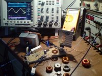
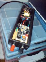
The important (to me) differences between typical Class D and this kind of amp are becoming clearer to me as I play around with it. I'm really quite taken by the results I've got from the initial design (just using a crappy LM393 and H-bridge for motor driving!). By making the Class A section into a modest but fully-fledged amplifier, and reducing the current sense resistor to around 0.1 Ohm the filter section doesn't seem to be all that critical. By this I mean it all seems happy driving a wide range of loads and there appears to be no need for any overall feedback. The reaction of the switches to the current error is the only loop and it appears to be quite well behaved (perhaps it's stabilised by the Class A drive?). Photo of lash-up below.
Attachments
payloadde said:Indeed, when I saw your proposal, P.Walker's current dumping from 1975 came to my mind, too.
Great info on the website quad405.com Many thanks for those links!
I have a question though concerning your project:
let's assume the A be a flawless amp, how accurate can the D follow ? For relaxed listening the output may be just 1 volt or so. If the D should follow this with no less than 0.1% deviation, the error signal would be a mere 1 milli volt. Can the error amplifier handle this ? Or is this a mute point because 5% iss good enough ?
I hadn't thought about this until you mentioned it... although I did wonder about disabling the bridge in the absence of signal (naturally it idles at 50% duty cycle). Maybe this would help.
OMG this is too easy: I'm sat here in almost total disbelief ~ I have a delicious Class A sound emanating from a handful of parts and tepid heatsinks! The bridge chip is supposed to run motors for goodness sake.
I haven't trusted it it anything other than a battle-hardened Tannoy Lynx (3169G - 100W 8Ohm 12" high sensitivity Dual Concentric) so far - but it's producing sounds every bit as musical as my MF amps are capable of (on a good day). The Tannoy's yield 95dB @ 50 - 20kHz for 2.8V so my diminutive 35V supply isn't holding me back from a reasonable audition.
The next step I think is to swap the bridge chip for a pair of IRF540Z's and I'm thinking of letting an LTLT1160 do the driving. I can't see this being any slower than what I have now: "180ns Transition Times Driving 10,000pFn - Adaptive Non-overlapping Gate Drives Prevent
Shoot-Through" Sounds useful. The obvious downside is the 60V top-rail limit. ABS. Max is quoted as 75V ~ in a "protective environment" (i.e. with varistor clamps on the supply rail) I might just stretch it to 70V to get 75Watts into 8Ohms. Even at 60V I will have more poke than the A1 and about the same as the A120...
...Mumble now I'm wondering how to get to 100W to give the Tannoy's something to really chew on.
Good work!
I think LT1160 is not a very good choice, the manufacturer does not advice to use it over 100kHz as far as I remember. Go for gate drivers from IR, like IRS2011 for example.
Also, you may like to get to know the SMALA concept, which works basically the same as yours except for it senses the current draw from supplies, so it is generally targeted to classAB.
P.s. 100uH and 10nF for LC filter? Its impedance is far from 8ohms! Why such values?
Are you using this over the full 20 - 20khz range ?
the sine on the scope looks good.
I cranked mine up to 1.35 Mhz and used a 15uH coil and .22uf cap as the output filter to achieve full range class A performance out of a class D amp.
the sine on the scope looks good.
I cranked mine up to 1.35 Mhz and used a 15uH coil and .22uf cap as the output filter to achieve full range class A performance out of a class D amp.
darkfenriz said:Good work!
I think LT1160 is not a very good choice, the manufacturer does not advice to use it over 100kHz as far as I remember. Go for gate drivers from IR, like IRS2011 for example.
Also, you may like to get to know the SMALA concept, which works basically the same as yours except for it senses the current draw from supplies, so it is generally targeted to classAB.
P.s. 100uH and 10nF for LC filter? Its impedance is far from 8ohms! Why such values?
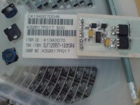
Thanks for the steer away from the LT chip. After a bit of digging around I decided on using the IRS20955 to drive a pair of IRF540Z's for my next attempt. Attached photo of PCB below. I'm trying to split the whole thing into modules like this as the design lends itself to modularization - and it will allow me to audition different sections along the way. BTW, the schematics did have one or two bum values after I (ahem) tidied them up before posting. Calculated values will appear in due course.
stocktrader200 said:Are you using this over the full 20 - 20khz range ?
the sine on the scope looks good.
I cranked mine up to 1.35 Mhz and used a 15uH coil and .22uf cap as the output filter to achieve full range class A performance out of a class D amp.
Excellent! Have you posted the project on these forums? I couldn't find any other examples of actual paralleled amps. As for range, yes I want all I can get!
Attachments
I was having some serious trouble with the IRS20955 - I killed four of them! But I finally got on top of the problem (documented in this thread: http://www.diyaudio.com/forums/showthread.php?t=148950) and now things are moving on nicely. I'm finding that the IRS20955 is very useful because it allows the PWM input to be referenced to mid-rail where the comparator is. I think has definitely been worth persevering!
I now have the "parallel amp" connected to a minimalistic transistor/resistor source follower: An IRFP240 with a 100R source load and thanks to the magic of Class D the O/P is driving about 75W into 4Ohms. I have adjusted the switch frequency to be 600kHz at idle and the Loudspeaker signal has approx. 100mV ripple on it. The sound is unmistakably "Pure Class A" and I'm about excited as a lottery winner!
Perhaps someone should try bringing me down to the ground by pointing out that a Class A preamp for a standard UcD ought to yield the same results... but I can drop the enable pin on the IRS20955 and still hear the music (albeit at lower input levels to prevent problems with -ve swing). Also, when looking at the O/P of the Class D when it's not "in parallel" it's clear how much the Class A damps down the carrier - even without any feedback.
And it's the elimination of feedback that I've been striving for all along: the reactance of the Loudspeaker seems to be of little concern to this particular circuit.
The experimental design is now boxed-up and running without any more tweaking. I've been comparing it with an old TRIPATH amp that I've got working again (see TRIPATH EB-TA0104 revisited ) and it's very much holding its own in terms of sound quality.
What I find seems to be the acid test for amps like these is playing around with an old analogue signal generator at high levels (only when the rest of the house is deserted!). At between 10KHz and my upper limit (13K and falling) fine-tuning the frequency reveals all the aliasing that happens as the carrier shifts with amplitude. Even at low amplitudes this has quite a nasty effect, but it's much more pronounced with the TRIPATH.
In the photos you can see an old ATX PSU case special dedicated to the trafo supply (I find these make great enclosures for quick-build projects like this) and the extruded case for the amp. It's a bit out of focus but the 100R 25 watt resistor that loads the follower is visible at the far end. Where the signal comes in there's a switch that controls the enable pin on the MOSFET driver chip and throwing this allows you to listen in pure "first watt" mode or with "Class D assistance". Unfortunately the only appreciable difference is a slight gain when Class D is used - presumably from the change in transconductance of the "unloaded" follower. Slightly louder always comes across as "better" but being critical it's not masking anything bad. I can't see why this approach isn't more popular!
Attachments

I once did simulations with paralleled amps. The circuit was some sort of first-order delta-sigma. It was mostly free of supply pumping and there was no switching at all at low signal levels. And only the switch for the side where power was drawn was operated when needed. Such a thing could of course also be built in a self-oscillating fashion and there is even an (Australian ?) patent for something like this.
It all looked promising but a pure class-d is still a lot more interesting to me.
Regards
Charles
It all looked promising but a pure class-d is still a lot more interesting to me.
Regards
Charles
It all looked promising but a pure class-d is still a lot more interesting to me.
That's cool - but I'm curious to know what you mean by "pure" class-d ~ there are many significantly different approaches to getting the switching signal. Do you mean comparing the signal with a sawtooth to get PWM?
By pure class-d I mean one with not linear output devices - neither in parallel nor serial (like tracking PSU).
Regards
Charles
Regards
Charles
- Status
- Not open for further replies.
- Home
- Amplifiers
- Class D
- Paralleled Class A with Class D