I have not built this yet.
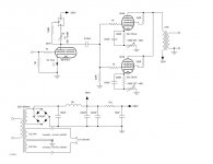
The grid leak resistor for the 6N1P should be OK since my preamp output impedance is low, < 600 ohms.
I'm not sure about the shared grid resistor for the 12W6. The data sheet says 500K. Is it correct to halve that? Will 220K be OK?
Any other critique is more than welcome. Thanks.
Scott
I just realized I forgot to label the CCS, it is a 10M45S.
Attachments
Last edited:
Scott,
I think that your cathode bypass capacitor is quite small unless you are using it to attenuate low freq. In addition, IIRC, the cap should bypass both the fixed and variable. I would also use the variable in parallel with the fixed (recalculated values of course) to reduce the power it needs to dissipate.
I can't see why the common grid leak will cause a problem. That will depend on output impedance of the driver tube.
Thanks for the reply.
Yes I suppose that would be correct about the bypass cap across both resistors.
I calculate a 1.85Hz -3dB corner frequency with 100uF and 860R.
The variable resistor in series only needs to dissipate 0.05W and it is a 0.5W device.
Yes I suppose that would be correct about the bypass cap across both resistors.
I calculate a 1.85Hz -3dB corner frequency with 100uF and 860R.
The variable resistor in series only needs to dissipate 0.05W and it is a 0.5W device.
Wattage of variable resistor is given for nominal resistance. If cathode current flows thru a fraction of it, then you have to take it into account.
Yes, with current flowing through a fraction of it would would need to dissipate less wattage. In this case the resistor will need to be set for about 40R.
Thanks.
Thanks.
Wattage of variable resistor is given for nominal resistance. If cathode current flows thru a fraction of it, then you have to take it into account.
Last edited:
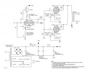
Updated drawing to show the cathode bypass capacitor for the power tubes across the entire resistor chain.
Although not shown on the drawing, each diode in the full-wave bridge is bypassed with a 0.01/2kV ceramic capacitor and 1M/1.5kV resistor.
Also, the 120uf capacitor following the bridge rectifier circuit is bypassed by a 10uF metallized polypropylene capacitor. The 56uF capacitor for the driver stage is bypassed by a 4.7uF metallized polypropylene capacitor.
Scott
Attachments
I've read that they work well for an audio amp. Well I've got a bunch of them as well as the 6N1P. Might as well try it out.
Although just one 12W6 at about 2 watts or so sounded kind of lame. So maybe I'll get to 3 or 4 watts with 2? We'll see.
Although just one 12W6 at about 2 watts or so sounded kind of lame. So maybe I'll get to 3 or 4 watts with 2? We'll see.
Last edited:
i use them for guitar amps and they are good, i am going to use them in a hifi amp as soon as i get the time....another tube is the 12EN7, looks exactly the same....
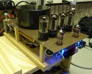
I built the circuit. All of the voltages measure as calculated.
The 100R pot in series with the 12W6 cathode resistor doesn't seem to have as much effect on adjust the bias voltage as I though it would. I've got 12 of the 12W6 and the bias range varies from 29V to 32V. The pot only allows about 1V of adjustment.
The paralleled 6N1P has plenty of drive for the 12W6s.
The amp sounds rather nice. I haven't done any extensive measurements yet, but I would guess I am getting about 5 - 6 watts.
Scott
Attachments
I've been listening to this amp every day for the past 2 months. I can't explain scientifically why it sounds as good as it does. It rivals the KT88SE kit that I offered based on the Mikael Abdellah design.
I did although use standard principals when I calculated the circuit parameters and values used.
I really wish someone here would build this thing and tell me that I'm not...well I know I'm crazy...but seriously, it sounds very good.
I'm currently using it with my Leach 2-way speakers that are 89dB sensitivity. My studio apartment is only about 18' x 22' and this amp is more than enough to get me in trouble if I crank it up. Great low, mid, and high end response.
Not that expensive. The 12W6GT are only $3.
Scott
Attachments
Last edited:
I use 6W6 to drive my SE 300B. Yes, it does sound very nice. Good driver tube.
Just keep it quiet.
Just keep it quiet.
Scott
I used 6W6 and variants in SE and PP and I know what you are talking about regarding sound quality. Congratulations on your amp!
Erik
I used 6W6 and variants in SE and PP and I know what you are talking about regarding sound quality. Congratulations on your amp!
Erik
Scott Can I use the 6W6GT tube instead of th 12W6GT? The 6W6GT in my country is cheaper than the 12 volt filament version
Antonio
Antonio
Scott I have other 2 questions:
Do I need of an 15W Output transformer? didn't it make just 5-6 Watt? if that is the power rating I could just buy a 10W OT.
and what is the load in mA of the B+ in this amp?
Sorry if they are newbie questions but I don't know much about Parallel Single Ended amps..
Antonio
Do I need of an 15W Output transformer? didn't it make just 5-6 Watt? if that is the power rating I could just buy a 10W OT.
and what is the load in mA of the B+ in this amp?
Sorry if they are newbie questions but I don't know much about Parallel Single Ended amps..
Antonio
- Status
- Not open for further replies.
- Home
- Amplifiers
- Tubes / Valves
- parallel single-ended 12W6


