You can use duncanamp's psud to get a good idea of the diode/transformer currents. It will do SS as well as vacuum rectifiers.
http://www.duncanamps.com/software.html
http://www.duncanamps.com/software.html
Max inrush current calculation - help
This threads appearance is timely for me as i am considering increasing the PS capacitance in one of my chip amps. I am new to this so please bear with me.
I think i can now calculate the theoretical peak inrush current (see below). but i am still unclear of how to adjust the calculation for real world factors. first i am unsure of what all the factors are. secondly, how do i adjust the calculation appropriately.
To better understand how to calculate peak inrush current i made a couple of plots.
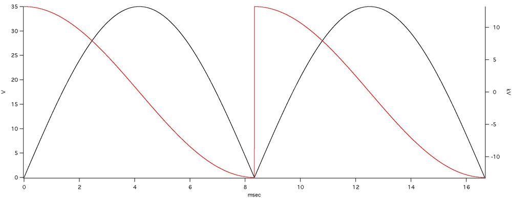
The black trace is a 60 hz sine wave that has been rectified (squared then took the square root).
The red trace is the differential(rate of change of the voltage) of the red trace.
The max dv/dt on this trace is:13194.7V/s
The parameters were all taken from the previous post (35V, 26800 micro Farads,60hz)
applying the formula i=C*dv/dt
i=26800e-6F*13194.7v/s=353.618Amps
This is significantly larger than BWRX's calculation of 235A (26800e-6*(35/0.4)).
assuming i did not make an arithmetic mistake, i have two questions:
1. why is theoretical calculation overly conservative (at least in comparison BWRX's). (Voltage drop at peak current? resistance of the capacitor?)
2. how can i adjust my calculation to account for these factors.
thanks.
This threads appearance is timely for me as i am considering increasing the PS capacitance in one of my chip amps. I am new to this so please bear with me.
I think i can now calculate the theoretical peak inrush current (see below). but i am still unclear of how to adjust the calculation for real world factors. first i am unsure of what all the factors are. secondly, how do i adjust the calculation appropriately.
To better understand how to calculate peak inrush current i made a couple of plots.
The black trace is a 60 hz sine wave that has been rectified (squared then took the square root).
The red trace is the differential(rate of change of the voltage) of the red trace.
The max dv/dt on this trace is:13194.7V/s
The parameters were all taken from the previous post (35V, 26800 micro Farads,60hz)
applying the formula i=C*dv/dt
i=26800e-6F*13194.7v/s=353.618Amps
This is significantly larger than BWRX's calculation of 235A (26800e-6*(35/0.4)).
assuming i did not make an arithmetic mistake, i have two questions:
1. why is theoretical calculation overly conservative (at least in comparison BWRX's). (Voltage drop at peak current? resistance of the capacitor?)
2. how can i adjust my calculation to account for these factors.
thanks.
the biggest missing factor is the series resistance through the transformer, connections and into the smoothing caps.
Even allowing only 0r1 for this total resistance around the whole charging circuit would require 23.5V or 35.3V to pass those currents through to the capacitors.
Now insert the remaining voltage into your charging capacitor formula.
Far easier to use Vpk/[total circuit resistance] and accept this is not particularly accurate, but far more accurate than omitting resistance as has been done already.
This peak lasts for less than a quarter of a cycle and the worst case peak value should be less than the peak capability of the diodes.
From experience, PSUD2 makes a good attempt at combining both methods and uses dynamic effects to give apparently accurate results with time.
Bobken said:Hi Jan,
Of course, such a current draw by a chip amp is impossible, as I suggested, as you would need massive and quite impractical heatsinking amongst other things, which is obviously not the case here with (any?) chip amps. We are probably dealing with a max. of 25% of this 8A capability in reality, which is why I don't forsee any real problems here, even with only one diode device being used.
The surge potential is not quite so clear cut, though, and this is why I continually suggested that caution should be adopted, at least initially. If the switch is flipped just when the mains is at a peak of the AC, and the smoothing caps are seen almost as a dead short, who knows precisely what this can do by way of instantaneous current draw?
I don't measure the characteristics of very many diodes as I haven't found it necessary for any matching purposes or whatever (unlike most other semi-conductors which I match as a matter of course), but recently for another purpose I did check a batch of fairly mundane diodes, and found that their forward voltage drops etc. were remarkably consistent.
It is academic now, but although I don't presently recall quite why Metaxas advocated this multi-parallel diode arrangement, my guess is that it was related to keeping the mains impedance as low as possible, as this does have a sonic effect with amps (like Class AB) which don't draw current consistently. For this same reason I would also avoid deliberately adding any resistance in this path, however low this might be, in order to 'equalise' parallel diodes. In my experience, it should not be needed, especially in this instance.
I have always been keen to encourage others to try things out for themselves, as I (and I suspect many others) have learned a great deal about these matters by so doing, and in my own case over a period of some 40 yrs. In this situation where the voltage is low, and with very little current draw to consider, I don't forsee any serious danger or disasters occurring, providing a little common-sense and care is taken by Daniel.
I hope that things go well for him, but I am sure the exercise will teach him something worthwhile, even if for some obscure reason it transpires that his chosen diodes are not quite up to the requirements of this job.
Regards,
One thing that is often forgotten is that the diodes do not conduct about 80% of the time. So, for 80% of the time, the only power available is that what is in the capacitor. So, trying to make the supply before the cap (diodes, xformer) very low impedance only comes into play the other 20% of the time, and translates itself in enormous peak currents that create a spray of high order harmonics of the mains that may radiate all over the place. Now, IF you use a reasonable xformer, or better yet, a fractional ohm resistor in series with the diode, you win on all fronts. Your diode get an easier job, your transformer noise (mechanical) goes down, and the voltage across the cap loses those sharp, harmonics-generating edges.
Jan Didden
Hi Jan,
" very low impedance only comes into play the other 20% of the time"
Of course, and that is why it is (if anything) more important to maintain a low 'dynamic' impedance here.
Caps or carefully-designed snubbers across the diodes are likely to have a more marked beneficial effect than any low-value resistor in series in my opinion, and they don't add any unwanted impedance here, but I don't care for what effect they have on the sound, either.
For what it is worth, I am not alone in this opinion, in spite of what theory & measurements suggest about this issue.
Regards,
Bobken said:Hi Jan,
" very low impedance only comes into play the other 20% of the time"
Of course, and that is why it is (if anything) more important to maintain a low 'dynamic' impedance here.
Caps or carefully-designed snubbers across the diodes are likely to have a more marked beneficial effect than any low-value resistor in series in my opinion, and they don't add any unwanted impedance here, but I don't care for what effect they have on the sound, either.
For what it is worth, I am not alone in this opinion, in spite of what theory & measurements suggest about this issue.
Regards,
Think it through. The 'low dynamic impedance' doesn't do diddly when the diodes are off. And that's 80% (give or take a few %) of the time, you realize that, don't you?
So how about the time that the diodes DO conduct? What is important is to charge the capacitors to top value before the diodes switch off again, correct? So, if you do it very, very fast, with a low impedance source, the only benefit is that you are 'done' before the diodes switch off, you don't use the time that is available. And what do you get in return? VERY high current pulses, very high diode stresses, and a sharp saw-tooth across the cap which means a lot of high harmonics. Which you will find back further in your circuit.
Think it through.
Jan Didden
I think the oversimplification has overlooked the fact that the difference in supply voltage and capacitor voltage is what charges the capacitors on each recharge cycle. The current is not infinite nor extreme. The voltage charges at the rate controlled by that basic capacitor charging formula stated earlier. All one needs to do is insert the driving voltage at each instantaneous moment in time. Once again it's worth pointing out that PSUD2 gives a nice picture and numbers of what is happening and when.janneman said:So how about the time that the diodes DO conduct? What is important is to charge the capacitors to top value before the diodes switch off again, correct? So, if you do it very, very fast, with a low impedance source, the only benefit is that you are 'done' before the diodes switch off, you don't use the time that is available. And what do you get in return? VERY high current pulses, very high diode stresses, and a sharp saw-tooth across the cap which means a lot of high harmonics. Which you will find back further in your circuit.
Think it through.
Jan Didden
It's also fairly easy to model various resistances in the circuits to see their effect.
AndrewT said:
I think the oversimplification has overlooked the fact that the difference in supply voltage and capacitor voltage is what charges the capacitors on each recharge cycle. [snip]
I agree Andrew. I was (deliberately) oversimplifying to try to move the reader away from 'everyone knows that...'.
But the effect is the same. With a very low impedance xformer you get more sharp current pulses (and stronger harmonics on the cap ripple wave form) then with an impedance that is matched to the application: an impedance that is sufficient to comfortably charge the cap at each half cycle (maybe even a few times larger for safety reasons), but not more. Doing more cost more and works out worse. Indeed, PSUD shows that neatly.
Jan Didden
Hi Jan,
I am not naiive enough to fall into the "everyone knows" trap, and I merely said that I am not alone in my findings.
Notwithstanding this, I do know from my own trials that adding impedance here does not improve the sonic results in the audio circuits I have experimented with, in spite of what theory might suggest. Therefore, I do not need "to think it through".
Why you would wish to divert attention from my straightforward statement in this respect by bringing the cost of low-impedance transformers into the matter, I cannot guess.
Have a happy Christmas.
🙂
Hi guys.
I will not elaborate the experience of others...I have enough of my own, having dealt with silicon from beginning to end. (probing 6 inch wafers of 1N4148's prior to dicing and mounting..they are about 12 mils (.012 inch) square.. up to 3 inch diameter diodes I personally assembled into 11 pound assemblies for use in liquid helium at 7000 amps. (perhaps not relevant to the discussion, but really fun to do..🙂 ))
1. Jan is correct, there can be current sharing issues with parallel diodes. When I parallel diodes, I keep the matching to within 1 millivolt at the maximum per diode current level, measured within a minute or two to maintain measurement temperature, and that is only diodes from the same wafer and diffusion lot. It is not possible for anybody outside of a diode manufacturer, to match in this fashion without additional and very expensive configuration controls imposed on the manufacturer.
2. Jan is also correct in using per diode resistances to stabilize the sharing of current. Without such, it is very possible for the assembly to go into thermal runaway, where only one diode conducts all the current.
3. I have not seen here, the issue of heat sinking. Axials are cooled almost exclusively via their leads. If there is a difference in thermal transfer, either transient or dc, one diode can easily hog the current. I've built testers to screen for this, but again, it is beyond most users and diy'rs..
4. Diodes are typically characterized for forward surge with a graph. Depicted is the current peak vs the number of pulses, normally as per a JEDEC method.. This can be exceeded by the user, but they do so at their own risk. What is good however, is that the data is usually presented as the peak surge superimposed upon the rated current, so there is some leeway. Note that rated current is supposed to be that which produces maximum junction temperature for a given lead length, and again that is usually derated a tad. I would not go over the graph, but I am a cautious person..
5. Jan is also correct in the description of capacitance total vs peak currents. This has some impact on the thermal peaks of the diodes, but it is a sawtooth temperature profile varying about an average temperature determined by the average current and the thermal transfer coefficients of the design.
6. Diodes used for power supplies do not have a 2.2 millivolt per degree C temco (barring shottkys). It is usually between .8 and 1.2 mV/C.. This is because they are being used in the high injection regime. The same diodes used at 10 milliamps will indeed exhibit about 2.2 mV/C. If you see a graph depicting anything else, or even data which crosses ZERO, it is incorrect. I found this problem with many motorola and IR catalogs, and it is a design flaw in both the test methodology and the test equipment used. I've not seen this corrected, and I first pointed this out within industry back in '84.
Overall, an interesting thread. Enjoy the holidays guys..
Cheers, John
Silly me, almost forgot..
7. The transient thermal response of the diodes is also important. The larger the die area, the more susceptible the silicon is to either thermal hotspots, or thermal cold spots. A thermal hotspot is one where the die attach has a void, allowing excessive heating at the area without compromising the initial current density profile, and a coldspot is where the current density profile is impacted, causing less heat at the area. Get around this via transient thermal matching, or use a tighter screening process. Again, outside the realm of most people to do.
Cheers, John
Daniel's diodes!
Hi,
John has now kindly confirmed several points of Jan's which are relative to using diodes in parallel, including that there "can be current-sharing issues" and "very possible for the unit to go into thermal runaway", and no-one (so far) has said that this is not the case. I have accepted that some diodes can be more variable in their characteristics than my previous experiences indicated, but I have never suggested that any diode should be operated continuously anywhere near to their safe upper limits.
Has anyone else noticed that on the 17th. (the last time he posted, so I do hope he is OK) the thread-starter Daniel said that he intended to use a single diode now, and because these are rated for 8A continuously, any need for *adding any resistance* for current-sharing or any safety-purposes is academic?
With a steady-state current capability amounting to probably 4 or more times the chip amp's likely max. requirement, as I have suggested this looks fine to me, but in all 'virgin' cases it is still wise to be cautious for the first few times, even when all components are operated within their SOA.
As I have also mentioned, the greatest chance of failure of one of these bridges is at 'switch-on', and (for Daniel's sake) I would not put my *entire* faith in any calculations made in respect of this instantaneous current-surge at 'switch-on'. Diodes do exibit different characteristics (as I originally advised Daniel), and electrolytics do as well, from one to another, even when of the same make and value. Unavoidable 'local' circuit impedances, as Andrew has mentioned, will have a considerable effect on this issue too, and I somehow doubt that it is possible/practical for these characteristics to be *precisely* factored into any equations to provide a definitive answer.
Several of John's other helpful comments now reinforce my views here, particularly in a case like this where it is likely that the initial surge current will be considerable, and could be close to, or possibly exceed that of the proposed diodes. The only certain way to know, is to 'suck it and see'.
However, this lack of confidence in theory or calculations only relates to the initial-surge potential problem, and has nothing to do with the normal operating conditions of such diodes in a case like this.
If Daniel is still in touch with this thread, I hope that he has not been put off and is still trying things out for himself, that he is OK and hasn't experienced any diode failures, and that he is adopting the cautionary stance which I have tried to impress upon him. I guess seeing some of the 'mixed' messages written since his stated intention to use merely a single diode, might have been a bit confusing to him. However, unless his single diodes fail in use, I still would not recommend that he *adds* any series resistance at this point of the circuit, as in my experiences this will not improve the sound, and will most likely have a negative effect, if anything.
Regards,
- Status
- Not open for further replies.
- Home
- Amplifiers
- Chip Amps
- parallel rectifiers