Hello folks,
just finished building/testing this "little" amp with what i had laying around.
Seeking for some advice on upgrades/help to spot some flaws. Still learning... as always in life 😀
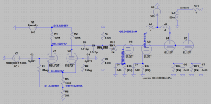
The Output tubes are VT52's by Marconi (electrically equivalent to EL32). Connected as triodes.
4 per channel (parallel push-pull).
the driver is a LTP with 6SL7GT.
AC coupling.
AC heater for all the tubes.
The psu is not posted, but very straightforward.
Full wave rectification done by a
5V4 -> 20uf -> 5H -> 150u ---> B+(output-tubes)
then B+(output-tubes)->1k->47u --->B+(driver stage)
No Global nfb.
The values of currents/voltages in the schematic is checked against the "real" model and they follows pretty close to what simulated.
Eager to know what you think.
Have a nice day/night 😀
just finished building/testing this "little" amp with what i had laying around.
Seeking for some advice on upgrades/help to spot some flaws. Still learning... as always in life 😀
The Output tubes are VT52's by Marconi (electrically equivalent to EL32). Connected as triodes.
4 per channel (parallel push-pull).
the driver is a LTP with 6SL7GT.
AC coupling.
AC heater for all the tubes.
The psu is not posted, but very straightforward.
Full wave rectification done by a
5V4 -> 20uf -> 5H -> 150u ---> B+(output-tubes)
then B+(output-tubes)->1k->47u --->B+(driver stage)
No Global nfb.
The values of currents/voltages in the schematic is checked against the "real" model and they follows pretty close to what simulated.
Eager to know what you think.
Have a nice day/night 😀
Attachments
Last edited:
gionag,
Looks pretty good! Triode Wired, and no NFB; probably sounds pretty sweet!
You have individual self bias resistors and bypass caps on the 4 output tubes . . . good. Makes it easy to swap tubes around until the DC current in Push is nearly the same as the DC current in Pull. Push pull output transformers like that.
You might want to put a 1k grid stopper resistor on each output tube grid, instead of just sharing one 1k per 2 tubes. Put the four 1k resistors directly on the four socket tabs.
The LTP 39k, R6, is not a perfect current source; so the output of the two 6SL7 plates are not quite the same amplitude (there will be a little 2nd harmonic distortion on the amp output).
You could use a current source (actually current sink) in place of R6, or . . . You could put a 10k pot wired as a rheostat (wiper connected to one end) in series with R2. Adjust the pot for minimum 2nd harmonic distortion at the amp output (or set it at 0 Ohms, and enjoy the small amount of 2nd harmonic distortion). Or anywhere between to "taste".
Let us know how what loudspeakers you are using.
Makes it easy to swap tubes around until the DC current in Push is nearly the same as the DC current in Pull. Push pull output transformers like that.
Fascinating point, never thought about this positive side-effect. How do you usually proceed to balance output tubes currents, where to measure ?
I will...You might want to put a 1k grid stopper resistor on each output tube grid, instead of just sharing one 1k per 2 tubes.
I would try to use the ixys M45 current regulator... or any other reccomendation is very welcome.The LTP 39k, R6, is not a perfect current source; so the output of the two 6SL7 plates are not quite the same amplitude (there will be a little 2nd harmonic distortion on the amp output).
They are "simple" Indiana Line 5.30. Not the ideal load for this amp... but good loudspeakers will be my next effort 😀Let us know how what loudspeakers you are using.
gionag,
One more thing, because there is 57 volts on the 6SL7 Grids, you may need to put some zener and steering diodes at the input to protect any solid state output stages that may drive the amp (like a CD player output).
As the amp warms up, and as it is turned off, the input capacitor is going to charge and then discharge respectively.
Connect a zener cathode to the input signal, and the zener anode to a signal diode anode, and connect the signal diode cathode to ground.
Connect a zener anode to the input signal, and the zener cathode to a signal diode cathode, and connect the signal diode anode to ground.
A 5V zener that has low leakage at 3V will not affect the output of a CD player at max output.
If you cannot test the zener leakage at 3V, then use a zener of the next voltage rating.
You should put a 1k Ohm resistor from the input connector to the zener and diode transient limiters, and another 1k Ohm resistor from there to the amp input.
Last edited:
I think all this protections are not needed if i swap for a CCSink.
but, as the input is decoupled, for the source to see the 57v of the grid the input coupling cap must fail (short)... i know that can happen. better safe than sorry.
Still don't understand how to balance output tubes for matching push and pulling current.
ideally the two tube on the "Push" side has to ... push ... the same amount of current of the tubes on the "Pull" side, but i still struggling to came across a method to measure that.
... just to come back to the grid stopper resistor, as this tubes has the G1 on top of the glass envelope, maybe i can attach resistor inside the cap-plug.
gionag,
Each cathode is at about 17V. Each self bias resistor is 680 Ohms. The current is 17 / 680 = 25mA
Match the 680 Ohm resistors (at least reasonably close).
Suppose the 4 EL32 tubes have the following volts: 17V, 17.5V, 16.5V, and 17V. Put the two 17V on the "Push" side. Put the 16.5V and 17.5V on the "Pull" side. That is a current match from push to pull. Just do the best you can to do a match, try more tubes if you have spares.
I missed the fact that the EL32 has a control grid cap, not on the socket. Take the resistor, connect it to the cap-plug, and connect the wire to the other end of the resistor. Then use shrink tubing over the resistor and wire.
A capacitor starts with 0 Volts across it. One end is at 0 Volts, then you connect 57V to the other end . . . and current flows until the capacitor has 57V across it. Then, when the 57V at one end of the cap goes away (amp turned off), the 57V charge that is across the capacitor causes current to flow to the rest of the circuit.
You have 57V across 39k Ohms, that is 1.46mA. I do not believe an IXYS45 will work well at 1.46mA, you might check the data sheet. A constant current sink that replaces the 39k Ohm resistor will still have ~ 57V across it. The issue of charging and discharging the input cap will still remain, there is still hope . . .
I am working on designing a negative voltage supply using the 6.3V filament winding (6.9V in my amp, I have to use series resistors for the 6.3V tube filaments). The idea is to use Schotkey diodes, resistors, and filter caps in order to produce a negative voltage for a discreet bipolar NPN transistor current sink. That will allow the grids of the input triodes to be at zero volts. Thus, no zener signal diode pairs required at the inputs.
The + / - 3V peaks from a CD player will only move the cathodes of an LTP splitter + / - 1.5V. If the input tube only needs about 1 to 2 volts bias, a low voltage negative supply, and a low burden voltage discreet current sink will allow the input grids to be at 0V.
Last edited:
Uh... ok, already did that. I was wondering about some "obscure" dynamic current balance.Suppose the 4 EL32 tubes have the following volts: 17V, 17.5V, 16.5V, and 17V. Put the two 17V on the "Push" side. Put the 16.5V and 17.5V on the "Pull" side. That is a current match from push to pull. Just do the best you can to do a match, try more tubes if you have spares.
And.... now i feel stupid. 🙁A capacitor starts with 0 Volts across it. One end is at 0 Volts, then you connect 57V to the other end . . . and current flows until the capacitor has 57V across it.
... checked, starts from 2ma up to 100ma. No luck here 😀I do not believe an IXYS45 will work well at 1.46mA, you might check the data sheet.
I think i know what you trying to do... use the winding of the heaters in series with a diode "reversed" to obtain a small negative voltage. not sure what is best method, i think a good one is to cascode two npn to have great Ac impedance, but my lack of knowledge makes me stop there.I am working on designing a negative voltage supply using the 6.3V filament winding (6.9V in my amp, I have to use series resistors for the 6.3V tube filaments). The idea is to use Schotkey diodes, resistors, and filter caps in order to produce a negative voltage for a discreet bipolar NPN transistor current sink.
cheers !
gionag,
You are doing very well. Keep it up.
I don't know whether I make more mistakes when I write about tube amps, or whether I make more mistakes when I build them.
Dynamic current balance is most easily measured with an FFT, looking at harmonic distortion. I have a digital scope with an FFT. You could also use a sound card and software. I use my Denon test CD 1kHz tone (very clean), instead of my signal (function) generator (not as clean). You can really see the effect when you use that 10k pot in series with the one driver plate load that I mentioned. Adjust the pot to null the 2nd harmonic (nulls are Very sharp). And watch the relation of the 2nd harmonic to the 3rd harmonic too. If you have the 39k Ohm in the LTP, be sure to put the 10k pot in the plate circuit of the un-driven triode, not the one that gets input signal. If you have a true very high impedance current sink, then put the wiper of the 10k pot on the driver B+ voltage, and put the 10k pot ends on the tops of the 100k plate resistors. Adjust for 2nd harmonic null. If you measure the 2nd harmonic at the amp output, you are actually nulling out the total of the input stage and output stage.
If you do not have a scope with FFT, or sound card and software, you might try adjusting the pot by listening to music.
Last edited:
Dynamic current balance is most easily measured with an FFT, looking at harmonic distortion. I have a digital scope with an FFT. You could also use a sound card and software.
..........
If you do not have a scope with FFT, or sound card and software, you might try adjusting the pot by listening to music.
Done with my SoundCard + Visual analyzer. Measure the input+output while with the oscilloscope i was monitoring the two outputs from the LTP anodes after cap. matched the curves as best as possible, but, i have some 2nd left in the output... maybe due to a dynamic current imbalance in the vt-52s (already sorted to make half's match in steady-state current draw).
Sure !then put the wiper of the 10k pot on the driver B+ voltage, and put the 10k pot ends on the tops of the 100k plate resistors
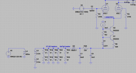
Please see attached idea for making a CCS for the LTP. Maybe the filament arrangement is total madness... but makes sense in my head.
Sure, I can easily fit a little another little transformer just to make a dedicated and more efficient negative supply, but maybe this solution is valid as well...
for the bipolars configuration i have referred to a textbook example... maybe something better is around, not sure about it...
Do you think my solution is usable ?
ciao!
Attachments
gionag,
I guess you have 12VAC there to work with. You should have plenty for the current source. But the peak inverse voltage across the 1N5817 is more than its 20V PIV rating; Use a 1N5819, it is rated for 40V PIV. Or you could even use a non schotkey, you do not need a low forward voltage drop. 12.6V x (1.414) x 2 = 35.6V. The first cap is at -17.8V, and the reverse voltage from the transformer is +17.8V (=35.6V).
I only have 6.3VAC, and a pseudo center tap, so I only used one transistor in my current source (an 'old' 2N3053 because it has an extremely high collector impedance rating).
One thing about your splitter and high frequency audio signals. You need to bypass R4 to ground with a 0u022 cap, so that the miller capacitance on the grid of U2 sees approximately the the same impedance at high frequencies as U1 grid sees. (The unbypassed R4 470k and miller capacitance will cause high frequency rolloff of U2).
There is some 2nd harmonic distortion on U1 and 2nd harmonic distortion on U2, but they are in opposite phase. I was using the 10k Pot (in both configurations I mentioned), to reduce the sum total of the 2nd harmonic of the inputs stages plus the output stages. That is why you need to measure the 2nd harmonic distortion at the amp output.
gionag,
I guess you have 12VAC there to work with. You should have plenty for the current source. But the peak inverse voltage across the 1N5817 is more than its 20V PIV rating; Use a 1N5819, it is rated for 40V PIV. Or you could even use a non schotkey, you do not need a low forward voltage drop. 12.6V x (1.414) x 2 = 35.6V. The first cap is at -17.8V, and the reverse voltage from the transformer is +17.8V (=35.6V).
I can understand that maybe was not 100% clear from the schematic.
at the moment, all the tubes of the left channel source from a 0-6.3v tap and the tubes on the right side from another one.
My idea is to make the heaters in series between each pair (in schematic 31 ohm is the heater from the vt-52 and the 21ohm is the heater of the 6sl7) of tube and then run between the who 0-6.3 in series with a leg grounded. I just wondering about current sharing between the two tubes...
then i can use the new 0-12.6 tap (6.3+6.3) to make a negative point for the CS.
as the AC impedance would be in the Mohm range, i think i can pretty safely share the same negative line on both channels without major crosstalking.
gionag,
There are tradeoffs.
Not all tubes of the same type have exactly the same filament current draw. So they may not have the same filament voltage if they are in series. That means if you can connect each tube across a 6.3V winding, that may be better than connecting 2 tube filaments that are in series across a 12.6V winding.
Because the input tube cathodes are at a very high impedance to ground, if there is any noise on the filament circuit (since the cathodes are unbypassed), it may appear on the plates outputs.
If there is enough voltage to use the 6.3 + 6.3 in series, and with the center of those two grounded; that would be less noise than grounding one end of the 12.6V and letting the center float.
The current sources should be able to share the same negative supply voltage.
One amp I have only has one 6.3V filament winding, and there is no room for a second filament transformer. My plan is to put two resistors in series across the 6.3V, and ground the center (pseudo center tap). That is why I will use a single transistor current sink, since I do not have enough negative voltage to use two transistors in series.
ok,
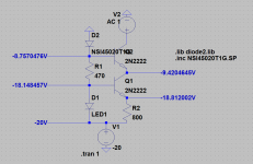
installed a new small transformer to generate a -16v voltage.
used the CCsink in the schematic.
the amp sounded better than ever and also the thd is went way down for the same amount of gain.
Yey, if i measure 2nd harmonic input to output still, with a 10k pot attached to load resistors i am unable to null it completly. i will try with an higher value pot, also because the gain of the driver is not so high, and maybe the +/-5k is not enough to generate a significant voltage diversity.
thanks for all the great info till now.
P.S. if i want to try a global feedback, in an ltp with CCS where i attach the signal coming from the output ? to the undriven grid ?
Attachments
- Status
- Not open for further replies.
- Home
- Amplifiers
- Tubes / Valves
- Parallel Push-Pull 6SL7GT + EL32 (Marconi VT52)