I agree, which is why I said "all else being equal".
In my own limited experience I have found that it isnt wise to assume two parallel tubes = double the power.
In reality it is more like almost but not double, and in fact I have found on more than one occasion, it is more reliable to assume 50% extra power, at slightly reduced THD, with the same reflected Z (OPT)
It was only when I moved from 2 to 3 parallel valves when changing the OPT tap made an improvement to performance, with 4 valves in parallel, eventually, I needed to half OPT Z to realise "double power" at equal performance to a single.
So I dont think it is as simple as a rule of two (theoretical assumptions, like lack of losses aside)
When paralleling triodes, the signal power goes up by +3dB, and noise power goes up by +3dB, Well . . .
Perhaps that is why there are not very many phono preamps that use 2 Parallel 12AX7 triodes for the input stage.
For input stages, signal is fixed, so S/N (definition constrained to Johnson/ "thermal" noise, and excluding current noise, a reasonable simplification for electron valves) increases 3dB with doubling transconductance.
Real phono stages are often dominated by 1/f, making most discussions irrelevant. "It's not irrelevant. It's a hippopatamus!"
YOS,
Chris
But if you do parallel two 12AX7 triodes, you reduce the plate load to be 1/2 of what it is for only one triode.
With the lower total rp, and the lower RL . . .
it can drive a lower impedance RIAA equalization passive network.
A lower passive network impedance is less effected by wiring capacitance, and the
Miller Effect capacitance of the next stage becomes less of an issue too.
Just another design tool if you choose to use it.
I've come to believe that the design of a single 12AX7 per channel phono equalizer is the most Zen experience a male of our species can have. (It may not compare to bearing a child, but I don't think I'd really want to experience that anyway.)
Arf!
Chris
Arf!
Chris
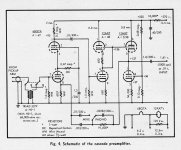
Bringing this thread back to ask a question. If I parallel the triodes of a 12AT7 cathode follower, and want to use separate cathode resistors as recommended in this thread by 6A3sUMMER, how is it wired at the output? By way of a concrete example, using this schematic, is it possible to have separate cathode resistors and parallel the two triodes in a CF?

tizman,
Please look at the schematic in Post # 1.
The parallel triodes are used as a 'common cathode stage'. The cathodes are 'common' to both the input signal and the output signal (because the cathodes do not 'move' along with signal voltage).
Therefore the words 'common cathode stage' is used, whether there is only 1 triode, or they are paralleled.
The output signal is from the parallel plates.
There is voltage gain from the input grids to the plates.
That is the circuit for which I suggested using individual cathode self bias resistors, with individual bypass caps across them.
That tends to make the plate currents equal for the two triodes.
Your schematic in Post # 45 is often classified as a 'common plate stage'.
Your circuit is different quite than in Post #1.
You can not apply my specific instructions about using individual self bias resistors for your circuit.
The plates are 'common' to both the input signal and the output signal (because the plates do not 'move' along with the signal voltage).
Therefore the words 'common plate stage' is used, whether there is only 1 triode, or they are paralleled.
The output signal is from the parallel cathodes.
There is a voltage Loss, the gain is less than 1 (less than unity).
However, I highly recommend using individual grid stopper resistors for each grid.
I say so, because I not only worked in Audio circuits, I worked in RF circuits.
From my work in RF, I see parasitic inductances of the wires, and I see parasitic capacitances of the wiring and the tube itself.
Parasitic inductance plus parasitic capacitances = Resonance (at RF frequencies, and tubes do work at RF frequencies).
At RF frequencies, I visualize your circuit loosley resembling a Buttler Oscillator. Ouch!
In my Posting in Tubes / Valves : "A Simple Low Power 7591 Push Pull Amplifier", I used a 'common cathode stage' 12AY7, and paralleled the two triodes.
You will note the individual grid stopper resistors; but with the IXYS constant current plate load, its impedance at RF frequencies, and all that wiring, I had oscillations.
So I inserted individual 1k Ohm resistors from each plate to the IXYS part; that killed the "Buttler-Like" oscillator.
RF is a funny thing, stuff happens that you would not expect.
Last edited:

Thanks for the clarification.tizman,
Please look at the schematic in Post # 1.
The parallel triodes are used as a 'common cathode stage'. The cathodes are 'common' to both the input signal and the output signal (because the cathodes do not 'move' along with signal voltage).
Therefore the words 'common cathode stage' is used, whether there is only 1 triode, or they are paralleled.
The output signal is from the parallel plates.
There is voltage gain from the input grids to the plates.
That is the circuit for which I suggested using individual cathode self bias resistors, with individual bypass caps across them.
That tends to make the plate currents equal for the two triodes.
Your schematic in Post # 45 is often classified as a 'common plate stage'.
Your circuit is different quite than in Post #1.
You can not apply my specific instructions about using individual self bias resistors for your circuit.
The plates are 'common' to both the input signal and the output signal (because the plates do not 'move' along with the signal voltage).
Therefore the words 'common plate stage' is used, whether there is only 1 triode, or they are paralleled.
The output signal is from the parallel cathodes.
There is a voltage Loss, the gain is less than 1 (less than unity).
However, I highly recommend using individual grid stopper resistors for each grid.
I say so, because I not only worked in Audio circuits, I worked in RF circuits.
From my work in RF, I see parasitic inductances of the wires, and I see parasitic capacitances of the wiring and the tube itself.
Parasitic inductance plus parasitic capacitances = Resonance (at RF frequencies, and tubes do work at RF frequencies).
At RF frequencies, I visualize your circuit loosley resembling a Buttler Oscillator. Ouch!
In my Posting in Tubes / Valves : "A Simple Low Power 7591 Push Pull Amplifier", I used a 'common cathode stage' 12AY7, and paralleled the two triodes.
You will note the individual grid stopper resistors; but with the IXYS constant current plate load, its impedance at RF frequencies, and all that wiring, I had oscillations.
So I inserted individual 1k Ohm resistors from each plate to the IXYS part; that killed the "Buttler-Like" oscillator.
RF is a funny thing, stuff happens that you would not expect.
Yes very easily, but there is really no need to do it.is it possible to have separate cathode resistors and parallel the two triodes in a CF?
Merlinb,
You are correct. Yes, you can have separate cathode resistors on a parallel triodes CF.
I apologize.
But please notice the very large addition of additional parts to do that, in order to essentially preserve the topology of the schematic in Post # 45
(The circuit that tizman wants to modify to have the individual self bias resistors).
The modified circuit has to have the cathodes driving the output coupling caps directly, and that complicates things for the cathodes that are no longer connected together.
68 Ohms x 2 = 136 Ohm individual self bias resistors (2 parts instead of one).
220k Ohms x 2 = 440k Ohms, from the grids to the now individual cathodes (2 parts instead of one).
1 uF / 2 = 0.5uF individual capacitors from each cathode to the output connector (2 parts instead of one).
100 uF / 2 = 50uF individual capacitors from each cathode to the output connector (2 parts instead of one).
We have to change the value of 4 parts, and add more 4 parts, for a total of 8 new parts . . . not too bad.
tizman,
Please let us know if you will use individual self bias resistors, and drive the output coupling caps from each individual independent cathodes,
like what I described above.
All,
When paralleling tubes, there is a need to use either individual self bias / individual adjustable fixed bias, or a need to use very well matched tubes.
I would refer them to the following:
The very last issue of Glass Audio: Volume 12, Number 5, 2000. The cover article is "Paralleling Tubes Effects". Good luck finding a copy of that.
Last edited:
Merlinb,
You are correct. Yes, you can have separate cathode resistors on a parallel triodes CF.
I apologize.
But please notice the very large addition of additional parts to do that, in order to essentially preserve the topology of the schematic in Post # 45
(The circuit that tizman wants to modify to have the individual self bias resistors).
The modified circuit has to have the cathodes driving the output coupling caps directly, and that complicates things for the cathodes that are no longer connected together.
68 Ohms x 2 = 136 Ohm individual self bias resistors (2 parts instead of one).
220k Ohms x 2 = 440k Ohms, from the grids to the now individual cathodes (2 parts instead of one).
1 uF / 2 = 0.5uF individual capacitors from each cathode to the output connector (2 parts instead of one).
100 uF / 2 = 50uF individual capacitors from each cathode to the output connector (2 parts instead of one).
We have to change the value of 4 parts, and add more 4 parts, for a total of 8 new parts . . . not too bad.
tizman,
Please let us know if you will use individual self bias resistors, and drive the output coupling caps from each individual independent cathodes,
like what I described above.
All,
When paralleling tubes, there is a need to use either individual self bias / individual adjustable fixed bias, or a need to use very well matched tubes.
I would refer them to the following:
The very last issue of Glass Audio: Volume 12, Number 5, 2000. The cover article is "Paralleling Tubes Effects". Good luck finding a copy of that.
Thanks for your replies. Please refer to my schematic to confirm that this is the proper way to modify the circuit if using both triodes. Are the 6K resistors to ground on the cathode correct, or is it better to have a single resistor there? If a single resistor is used, what value should it be?Yes very easily, but there is really no need to do it.
Most importantly, are there any upsides to using the separate cathode resistors? Merlinb states that there is no need, but if there are any advantages, I do have all the required parts on hand.
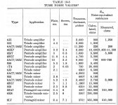
Vacuum Tube Noise is inversely proportional to the tube operating gm.
High gm tubes have less noise. Triodes do well.
Pentodes perform to a lesser degree, due to partition noise, caused by a
division of the cathode current between the plate & screen grid.
A very big issue for receivers, not so much in audio. Unless it is a preamp for a magnetic pickup.
Refer to the table lifted from a text book of the socalled 'Golden Era of the Vacuum Tube'.
And a real low noise front end.
Attachments
The article referenced measures distortion, not noise. 🙂When paralleling tubes, there is a need to use either individual self bias / individual adjustable fixed bias, or a need to use very well matched tubes.
I would refer them to the following:
The very last issue of Glass Audio: Volume 12, Number 5, 2000. The cover article is "Paralleling Tubes Effects". Good luck finding a copy of that.
Thanks for the info John!Vacuum Tube Noise is inversely proportional to the tube operating gm.
High gm tubes have less noise. Triodes do well.
Pentodes perform to a lesser degree, due to partition noise, caused by a
division of the cathode current between the plate & screen grid.
A very big issue for receivers, not so much in audio. Unless it is a preamp for a magnetic pickup.
Refer to the table lifted from a text book of the socalled 'Golden Era of the Vacuum Tube'.
And a real low noise front end.
If you are driving a 3k load, you do NOT want a puny 12AT7. Even in cathode follower, large low-THD swing wants rp much less than load. rp of a whole 12AT7 is like 22k/2 or 11K, you want 3K. Four whole 12AT7 gets you there with a lot of drill/solder labor.parallel the triodes of a 12AT7 cathode follower
2A3, 300B, 6V6, 6L6 (as triode) will not strain so bad.
Yes the 12AT7 can swing some voltage into 3k at sub-1%-THD, but the big bottles do better.
White Cathode Follower, carefully trimmed to a narrow range of loads, can null 2nd harmonic and make 3rd etc dang small, even into a short. But when it clips it is awful. And it has less peak output than the parallel CFs.
Or is this all about using-up excess 12AT7s?
Many amps use emitter resistors to balance them out.Paralleling is good.
The same goes for paralleling Transistors in power output stages.
Unless the transistors are closely matched.
I have a McGregor mixer/amp that used 4 mosfets in push pull output stage without source resistors.
It's mostly about providing a transparent volume control for a DIY Aleph J with a 250K Ohm input impedance. I built a preamp a while ago, mostly on a whim, but never use it as all of my DIY tube amps have enough gain with regular sources. and with my very sensitive speakers. The Aleph J is a new build, with too much gain for my setup, and no volume control. I kept the power supply of the previous preamp intact, but removed the circuit. This leaves me with two holes in the chassis, with two 9 pin tube sockets in the holes. I don't need any gain, so paralleling the two triodes of each tube for a CF makes sense. I have way too many 12AT7s, 12AX7s, 12AU7s, 6SN7, 6SL7, 6N1P-EV and 6N2P-EV, and a few 6922 and 6DJ8.If you are driving a 3k load, you do NOT want a puny 12AT7. Even in cathode follower, large low-THD swing wants rp much less than load. rp of a whole 12AT7 is like 22k/2 or 11K, you want 3K. Four whole 12AT7 gets you there with a lot of drill/solder labor.
2A3, 300B, 6V6, 6L6 (as triode) will not strain so bad.
Yes the 12AT7 can swing some voltage into 3k at sub-1%-THD, but the big bottles do better.
White Cathode Follower, carefully trimmed to a narrow range of loads, can null 2nd harmonic and make 3rd etc dang small, even into a short. But when it clips it is awful. And it has less peak output than the parallel CFs.
Or is this all about using-up excess 12AT7s?
Paralleled sections of the 6DJ8 would do the deed.
When dealing with the cathode resistor of a CF, treat it the same as we would if it were in the plate lead.
In other words, Rk should be at least 3 to 4X the rp of the tube at its operating point.
In the case of paralleling the tube sections, Rk can be 1/2 of that since we would have double the gm to work with.
Paralleled sections of the 6DJ8 would do the deed.
When dealing with the cathode resistor of a CF, treat it the same as we would if it were in the plate lead.
In other words, Rk should be at least 3 to 4X the rp of the tube at its operating point.
In the case of paralleling the tube sections, Rk can be 1/2 of that since we would have double the gm to work with.
Is this what PRR meant by driving a 3K load? The two 6K in parallel being the 3K? A 12AT7 is what I will probably end up using. I used the schematic from my earlier post as an example to refer to in order to ask how separate cathode resistors would be wired to two triodes, but it isn't the schematic I will use when modifying my preamp. Assuming that I use a 12AT7, the attached schematic is the one I would base my circuit on.If you are driving a 3k load, you do NOT want a puny 12AT7. Even in cathode follower, large low-THD swing wants rp much less than load. rp of a whole 12AT7 is like 22k/2 or 11K, you want 3K. Four whole 12AT7 gets you there with a lot of drill/solder labor.
2A3, 300B, 6V6, 6L6 (as triode) will not strain so bad.
Yes the 12AT7 can swing some voltage into 3k at sub-1%-THD, but the big bottles do better.
White Cathode Follower, carefully trimmed to a narrow range of loads, can null 2nd harmonic and make 3rd etc dang small, even into a short. But when it clips it is awful. And it has less peak output than the parallel CFs.
Or is this all about using-up excess 12AT7s?
This is the version modified to reflect using two triodes instead of one. I added R1 and R2 grid stoppers, and I think I did it mostly right, but I’m uncertain about the way that C2 and C3 are connected to R9 and the output. Is this correct?

https://www.enjoythemusic.com/diy/1108/sstart.htm
Gives a pretty good starter on benefits of paralleling devices, and is inspired by the Conran Johnson...
Gives a pretty good starter on benefits of paralleling devices, and is inspired by the Conran Johnson...
- Home
- Amplifiers
- Tubes / Valves
- Parallel operation of triodes.