What's the difference in noise performance of two triodes in parallel ( Anode, grid and cathode connected directly in parallel ) and one with a common anode load and separate cathode resistors with bypass capacitors ?
Unless the sections are very closely matched , the direct connection will not ensure identical operation of the two sections. Which is a better way to operate in 'parallel' ?
Conrad Johnson had a design with 12 tubes in parallel. How did they do it ?
IIRC some designers claim that parallel operation of tubes ( or even SS chips) sound worse than single device operation.
Is this observation confirmed now ?
Cheers,
Ashok.
Attachments
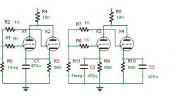

2 in parallel will give half noise and double the gm (gain). The usual method is to tie the G, K and A directly together. I'm not sure of the good or bad effect of having separate cathode bias circuits.
Ashok, that's correct, the noise of each section is uncorrelated, so you only get 3dB noise improvement from paralleling. Separating out the bias won't really change that.
There's no reason from an electrical standpoint that a parallel arrangement should sound worse, but I admit it's entirely possible to cause issues because of layout, grounding, and the like when doing that with actual tubes and wires.
There's no reason from an electrical standpoint that a parallel arrangement should sound worse, but I admit it's entirely possible to cause issues because of layout, grounding, and the like when doing that with actual tubes and wires.
ashok said:Which is a better way to operate in 'parallel' ?
Depends of the tubes gm in the sum. Separate cathode resistors increases the operation point stability (decreasing gm for DC).
The "borderline" is IMHO a gm > 10 ma/V for the tubes in parallel.
Andreas
IMHO, paralleling tubes equals increasing the max power, the slope, and reducing the internal impedance (in a rate of 2 for tube doubling) . But the "single plate" of a 300B for example is by itself a twin plate 😉 as the 6080 is 😀 one "right" anode , one "left" anode together tied , around a single cathode 
I used up to 4 sections of 12AX7 in parallel in some of my early phono pre-amplifier designs, this in and of itself resulted in about a 6dB improvement in noise performance.
The design only proved to be tolerant of mismatch between sections when individual cathode bias resistors were used. (higher distortion and lower gain without individual biasing)
The source impedance of that first stage was 1/4 of what it would be with a single tube meaning that the passive eq network could be scaled downwards accordingly which also resulted in some (significant) improvement in noise performance.
Sounded very good actually, these days I just cut to the chase and use triode connected D3A instead - sound even better and far quieter than even 10 or so 12AX7A sections in parallel and with a lot less miller capacitance - the downside of paralleling so many devices.
edit
Parallel operation of o/p stages is highly recommended, the near halving of output transformer Z reduces copper, improves b/w and easier to design o/p transformer. Related to another thread, with parallel o/p concept, UL operation will completely outstrip triode performance. Naturally the pSU becomes the other issue as stage current goes up and larger chassis.
Parallel tube operation of the p-p output stage doesn't quite follow the "halving Z rule" for optimum output stage performance. Shall have to read up on this.
richj
Parallel tube operation of the p-p output stage doesn't quite follow the "halving Z rule" for optimum output stage performance. Shall have to read up on this.
richj
* revives thread *
1) ...but surely tubes have such wide tolerances that two or more tubes of the theoretically same type in parallel will all be exibiting (slightly or widely) different characteristics, so will that increase distortion?
2) When paralleling tubes in a line stage (such as is done by CJ) which parameters require the closest matching for best objective performance of the completed stage?
Paralleling is good.
The same goes for paralleling Transistors in power output stages.
The same goes for paralleling Transistors in power output stages.
John wrote about it 20+ years ago... The Tube CAD Journal: Parrell tubes
I parallel triodes all the time, mostly for power duty though. I use current sharing resistors on the plates of about 10R to stop dumb oscillations.
I parallel triodes all the time, mostly for power duty though. I use current sharing resistors on the plates of about 10R to stop dumb oscillations.
Matched Parallel Tubes are not always matched for all circuits, currents, and voltages.
For Fixed Bias, use separate cathode sense resistors, and separate grid bias adjustments.
For Self Bias, use separate self bias resistors each with its own separate bypass cap.
I (and 2 others) wrote the cover story about this in Glass Audio, Volume 12, Number 5, year 2000.
Over 600 measurements, data correlation of currents, voltages, and harmonic distortions.
3 Listening Venues, Taylor Series Math, and other proofs.
There were tests for parallel driver tubes, and parallel output tubes.
Unfortunately, there are no longer magazine copies that you can get (Un-obtainium?).
Later, at VSAC 2003 (Vacuum State of the Art Conference) in Silverdale Washington, I gave a presentation of the essence of the circuits, measurements, and proofs.
But the conclusions of parallel tubes is that they work well . . . if all the correct methods and hints and kinks are properly implemented.
Higher current drive to the parallel grids; lower impedance loads to the parallel plates, higher current plate loads, more laminations (more Watts); separate grid stopper resistors; and proper separate biasing for each tube.
That pretty much covers most of it.
A 1/2 impedance (70% windings), larger laminations for 2X power, and wire for 2X current does not have less copper, versus the original 2X higher impedance, lower 1/2 power transformer. Larger laminations means longer wires for each turn, but we need 2X the current capability, and 1/2 the DCR of the original single tube OPT.
More proper implementation details.
For anybody that is having noise problems with output tubes, it is most likely faulty tubes, faulty circuits, or for DHT faulty DC filament supplies; . . . or else we are trying to fix the inner layers of an Onion, before we have even peeled the outer layers off the previous stages that drive the output stages.
Last edited:
Curious if you used test equipment as well as the ear of the group? My ears are my test equipment as far as distortion goes but it'd be interesting to quantify against "cold hard" measurements.
kodabmx,
As I said there were 600 measurements of current, voltages (DC and gain), and harmonic distortion.
The measurement population consisted of 20 dual triode tubes (population 40 triodes). some triode pairs were combined, and some triodes from different envelopes were combined. So for 2 dual triodes, there were multiple combinations of which triodes were paralleled. The signal source was an extremely low distortion sine wave source. The harmonic distortion measurements of the tube(s) output signals included down to -85dBc or lower, and up to the 8th harmonic whenever any showed up as high as that harmonic number. These measurements included non parallel triodes, and then paralleled triodes. Whenever the triodes were paralleled, the two loads were paralleled, so each tube saw the same load impedance. The 600 careful measurements were totally separate to the listening tests that occurred later.
Because of the skepticism of just doing measurements, the listening tests were next. The 3 listening venues used 3 different loudspeaker pairs, one unique pair only used at one of the 3 locations. There were 2 driver tubes, and 2 output tubes. Two dual position switches (that activated relays) allowed for the following settings:
1 Both Drivers and Outputs not paralleled
2 Drivers paralleled, and Outputs not paralleled
3 Driver not paralleled, and Outputs paralleled
4 Both Drivers and Outputs paralleled
This was a double blind test. None of the listeners knew what was being tested. They were merely told to note any differences of sound for the 4 combinations of the switch positions (down down, up down, down up, and up up) Even the test administrators did not watch the switch positions that the listeners set, so the administrators could not know what was paralleled or not. At one venue, one listener was so mad because he could not hear any differences for the 4 possible switch position combinations, so he threw the switches and umbilical cord across the room. For the 3 venues, the only listeners who were present at more than 1 venue were the test administrators. But the consensus of almost all but one of the listeners was that there was no detectable/hearable difference.
That was not enough proof for some minds, so next the Taylor series and Child's Law was used to calculate/describe the action of separate triodes and parallel triodes as it applied to both even harmonics, and odd harmonics (to see if the harmonics combined naturally or got worse, or got better than the un-paralleled operation).
This is still enough, so a persuasive argument was created. Take your 300B (or your favorite tube), and look at the exact spacing of the filament/cathode, to grid, and to plate to each, and then note that there is the other side of the tube that will have (even in a small amount) the exact spacing of the filament/cathode, to grid, to plate. A single tube already IS a paralleled tube. About the only exceptions to this are a few Planer Triodes of such construction as the 416A.
The key to successful paralleled operation is paying attention to exactly the parts used, and how to design the rest of the circuit. Of course, you also need to use tubes that are at least are in the same ball park. A triode that tests 95% on a tube tester is not going to combine well with a triode that only tests 55% on the same tester (not when the new paralleled load is 1/2 of the load impedance that was used for each single triode).
I hope that covers the subject a little better for you.
Last edited:
Wavebourn,
Yes, evenly placed spacing is not the only item.
Manufacturers may not use exactly the same coating on the filament (DHT) or the same coating on the cathode (indirect heated).
Manufacturers may use gold coated grids, or may not use gold coated grids.
Manufacturers may use circular plates, others rectangular plates, others square plates (i.e. 6SN7.
Manufacturers may use simple steel plates, others coated plates, others layered plates.
You have secondary emission and what happens with different plate materials and grid coatings.
You have different levels of vacuum pumping.
You have different placement of getters.
You have different chemicals in getters.
How many other items did I overlook or forget?
How matched are your tubes, even from the same manufacturers over decades of production. Some later ones may have even been built on contract from another manufacturer, and labeled as if made by the other company.
Electrons launch from the filament (DH) or cathode (IH) in different directions, from different places along the filament or cathode. What are the strongest fields for a given electron, as it relates to spacing, shape, etc. of the particular tube.
But the original point of a [definitive] study done and published in Glass Audio was to prove a point. In fact it was expected that it would be easy to hear the difference between non-paralleled and paralleled tubes. The conclusion was just the opposite.
If you know of the famous Michelson Morley experiment, it was designed to prove that Ether Did exist . . . but it did just the opposite . . . Ether does Not exist.
That was the same thing for the paralleled experiments . . . the desire was to prove that paralleled tubes do Not sound as good . . . but of course it proved just the opposite . . . paralleled tubes Do sound as good.
If you have experienced paralleled tubes that did not sound as good, then there was something wrong with the parts, circuits, or implementation.
So, the conclusion is, only a bit of maximal power depends on how well tubes are matched?
Cool! 🙂
Cool! 🙂
Using proper techniques, they generally do not have to be very closely matched.
But they should at least pass reasonable tube tests well.
One important thing that was discovered in the tests that became the magazine article. . . when you combine the plates to a 1/2 impedance and 1/2 DCR load, you must not connect the cathodes together (to a common 1/2 resistance self bias resistor).
Using a common self bias resistor absolutely requires Very close matching of the tubes, or the harmonic distortion will have anomalies.
The most common causes of failing to get good sound from paralleled tubes are:
Not using separate bias for each tube
Not using 2x the driver current capability (increased capacitance of the driven stage)
Not using a transformer load that is 1/2 impedance and 1/2 DCR
Not using a transformer that is 2X watts capable
Not using a power supply that is 2X current, and same ripple/regulation at that 2X level
. . .
and using one bad tube in the pair. For this discussion, what is a bad tube . . .
If you would not use one tube for a right channel of a single tube SE, and another tube for the left channel of a single tube SE, because one tube was weak(er) (and you like matched channels), then why would you take those same two tubes and parallel them for a mono-block amplifier?
The requirements for parallel SE and parallel Push Pull are the same in these regards.
Last edited:
6A3,
Couldn't find my old magazines so I have a question I hope you may be able to answer. What were your findings with respect to paralleling line-level dual triodes? Was there a benefit to it?
I'm designing a mono amp that will use a high-ish mu dual triode, possibly a 6SL7, as a simple VA first stage. Similar to EICO 87. So I have a spare half tube I could parallel.
I see the benefits being 2x gm and lower noise. Neither of which are a real issue in my scenario.
On the down side, I see 2x Miller and separate cathode bias resistors get a bit complicated because of GNFB.
Based on your experiments, does it make sense to parallel? And did you see a difference with separate cathode biasing? Again, for signal tubes, not power. Thanks.
Last edited:
- Home
- Amplifiers
- Tubes / Valves
- Parallel operation of triodes.