Hi all. Just wanted to be sure, when running DHTs in PSE it is okay to series the heaters correct? Then bias as per usual. I know with IHT I would bias with half value letting the 2x current be split between the triodes, but I figured for DHT I would run the regular values connected to the positive on both triodes and then to ground. 6 and a half dozen of the other as far as final values, except for that then one triode doesn't see an extra filament in its current path. This will be a negatively biased amp so final balance can be done there.
And, if anyone knows of any examples that would be great. Amp is a Parallel GM-70 SE. I'll be posting more as I get it going, almost finished with chassis and circuit this is o elf the last questions. Thanks again,
KB2WYL Loren
And, if anyone knows of any examples that would be great. Amp is a Parallel GM-70 SE. I'll be posting more as I get it going, almost finished with chassis and circuit this is o elf the last questions. Thanks again,
KB2WYL Loren
I usually connect the heaters in parallel or use separate filament supplies. If the heaters are connected in series the effective bias on the two tubes will differ significantly by virtue of their different potentials with regards to the bias point if cathode biased or circuit ground if fixed biased.
In general my feeling is that if you need PSE with DHTs choose the next larger DHT. Getting tubes that match dynamically is very difficult and unmatched tubes can degrade distortion performance.
In general my feeling is that if you need PSE with DHTs choose the next larger DHT. Getting tubes that match dynamically is very difficult and unmatched tubes can degrade distortion performance.
Thanks Kevin
I have the parallel option too, I should have included it in my query. I suppose I could go bigger but the GM-70 is just such a nice tube in its linearity/availability/price. My next question was going to be about the distortion byproducts anyhow, and now you have already mentioned it. I searched but have not been able to find very much info regarding the combination. This whole thing stems from getting my hands on some huge Silk Thailand OPTs that are made for Parallel GM-70, otherwise I would have just designed a single gm70/845 amp. Can you point me in the right direction of any reading material pertaining to the interaction of parallel DHT's and ways to combat the distortions caused by imbalance? I figured that it wouldn't be too bad since I won't be pushing them very hard. Most designs running class A with the GM70 SE realize around 18-24W, and my thought was that if I set it at 2v=30W out I would stay well enough within the limits that I wouldn't have much more than any other SE design with a single pushing 24+ in A2...No?
Thanks again,
Loren KB2WYL
Hi Loren,
The GM-70s are low enough cost to buy more than you need, and match them as best you can. I would set them up with a current-sense resistor, and measure the small-signal gm at the operating voltage/current you plan on using. This gives the best match for real-world quiet listening - what really counts!
You can also force the gm and bias to match a little better with some resistance is the « cathode » return connexion. If this is unbypassed, it decreases and converges the gm, slightly, and should help counter the distortions.
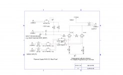
My schematic shows how I do it...
The GM-70s are low enough cost to buy more than you need, and match them as best you can. I would set them up with a current-sense resistor, and measure the small-signal gm at the operating voltage/current you plan on using. This gives the best match for real-world quiet listening - what really counts!
You can also force the gm and bias to match a little better with some resistance is the « cathode » return connexion. If this is unbypassed, it decreases and converges the gm, slightly, and should help counter the distortions.
My schematic shows how I do it...
Attachments
Thanks Rod
I was thinking about getting some more regulators from you, the ones for the 300b's were great, But first was going to go the old route. If I run the GM-70s in parallel I will have plenty of room for a CLCLCR setup on the filaments. I get what you are saying completely, and thank you, but seems like I could come up with a further balance scheme if the Gm-70s are in parallel. Maybe something like 47 ohm on each instead, and then a 10ohm with wiper to ground in the center..:;balance that for a bit better GM balance and then compensate with the bias voltage (adjustable for each tube). Yes?
Thanks all,
Loren KB2WYL
Rod's proposed solution is a good one, did not know you already had the transformer. I use GM70s in my amps with an earlier version of the filament regulator, I'd probably not use anything else at this point given the surprising sensitivity to other components in the filament supply. I'm using the latest version in my new line stage with the EML20AM and can report it is an improvement over the older version.
Rod is not supposed to plug his own product obviously, but I am more than happy to do it in his stead.
Rod is not supposed to plug his own product obviously, but I am more than happy to do it in his stead.
Could you clarify
A little bit Kevin? You probably wouldn't use anything else (meaning using Ron's boards) given the surprising sensitivity to the other components (meaning the rectifier and choke and caps?)
I agree on Ron's boards, and am happy to plug them. Probably will use them in end. But I'm curious what you meant exactly because at first I plan on using the normal CLC, and then measuring the difference with CLCLC. I'm sure it's an improvement, to what degree we will see. And I'm sure regulation will be a further improvement.
Guess the way I read it is that you wouldn't use anything else given the fact that his boards are very sensitive to what is before them, so in any case I would sure appreciate clarification. And maybe you have an opinion on the case of diminishing returns of further filtering after CLC without using regulation?
Thanks both of you,
Loren KB2WYL
the next (fourth) SE GM70 i like to built its parallel SEP, i tink of hammond 1642SE OPTand driver 211 by IT, wich one i do not now. you goin to use capacitor coupled?
individual bias trim and individual TP for each tube you check for 0mV between katodes will be ok
for heater hyperfast rectifiers bridge and common mode choke CLC give good result so i will follow your tread , please tell us more.
individual bias trim and individual TP for each tube you check for 0mV between katodes will be ok
for heater hyperfast rectifiers bridge and common mode choke CLC give good result so i will follow your tread , please tell us more.
Attachments
It will be IT coupled with Lundahl 2756..
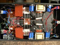
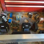
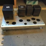
Here's a couple of pics...I'm almost finished drilling the chassis. I will post more later and schematic and all that as I get into it...for now just keeping on this parallel/balance/distortion topic. One thing at a time 🙂 Thank you very much for the interest though, like I said more to come and I'll start another thread for it. Hopefully the pics come through Im on a phone right now.
So while I wait for Kevin, I'm also curious Ron how did you arrive at those values for the Cathode resistors? I will probably have 2 in series as one will be a smaller sense resistor for one of the meters (extra rounds you see in the chassis)
Thanks all,
Loren KB2WYL
Attachments
Loren, big electrolytics seem to be audible in the filament circuit in most cases where I have gone completely passive. I have been burned more than once, one little board or lots of caps in parallel with some series resistance after the cap bank. Where it is really cost sensitive I often use a single LT108x as a CCS, where cost is not an issue I use a monolithic regulator ahead of Rod's CCS boards. This has always yielded great results for me.
My speaker system has a sensitivity of 100dB @ 1W and with room effects there is significant lift at 40 - 60Hz, 100uVrms of hum on the output of the amplifier is audible from six feet away. (The system is equalized but all equalization is before the amps)
My speaker system has a sensitivity of 100dB @ 1W and with room effects there is significant lift at 40 - 60Hz, 100uVrms of hum on the output of the amplifier is audible from six feet away. (The system is equalized but all equalization is before the amps)
Thank you, Kevin!
Loren, the resistor values were set to diminish gm by about 15-20%. Since you only want to run soft, this should be no problem.
And, yes, you can use dissimilar values, and try to match the effective gm.... or you can insert a pot for testing, and look at the output spectrum, and adjust until you like it best.
If you use dissimilar values, and optimise and adjust them, the values can be lowered, too.
The extreme component-sensitivity question arises only when you use an all-passive filament heating solution. When purpose-designed current-drive Regulators are used, the influence of passives diminishes greatly.
With properly designed Regulators, the quality of the Raw dc may still improve the sound though: for example, changing to LC raw dc filtering reduces the repetitive peak currents in the power transformer/rectifier/wiring - which can mean reduced coupling of these pulses into the signal wiring and parts in DAC and preamps, etc.
This effect of the raw dc quality upon the sound depends on how well optimised the general layout is to begin with... I try to keep power transformers & rectifiers away from sensitive areas.
Parallel GM-70 Amplifier
Hi all. I promised in another thread that I would start posting pics when I actually got going on this project. It's that time. Wanted to ask first though...
Anybody out there seen any schematics for a Parallel GM-70 amp? Or, any other transmitting triode parallel SE amp? Couldn't find much, and I'm still looking for more info on output tube balance in a parallel SE DHT design.
I found one amp that SILK Thailand made that was a parallel GM-70. The Glow Master GM-70. This project started because I have SILK Parallel GM-70 OPT's, otherwise I would have just done single SE. Anyway, the Glow Master has amazing specs. Full power is around 60W with 1.58% almost all 2nd order. 1W is a staggering .079....very impressive. And they are using 3 stages, with IT and then Cap coupling, where as I was planning on 2 stage IT.
So yeah, I'll start posting some pics. The HV, bias, and heater main supplies I already have PSUD'd, and laid out, so I'm starting there. But if anyone has any Schematics they'd like to share (Silk hasn't responded, and I doubt they will), I would sure appreciate the comparisons.
Thanks all,
Loren
KB2WYL
It was this thread that I promised in, sorry for the confusion Kevin. Now I understand the merge. So yes, if anyone has any schematics or first hand experience with this I would really appreciate any insight. Any knowledge is good knowledge. Like I told Kevin, I've done DHT, and Parallel SE, but this is my first foray into both worlds combined. Thanks all,
And I will post pics soon
Loren
KB2WYL
And I will post pics soon
Loren
KB2WYL
Pretty much the same rules apply, matching is important as is some way to deal with slight mismatches between tubes.
Are you considering fixed bias or cathode bias in the output stage?
What sort of coupling between the driver stage and the output stage are you considering?
I've not seen any GM70 parallel designs, but there is no reason you couldn't do it, and I would confess that I have not looked hard as 20W was all I really needed.
Thanks Kevin
So I am aiming at fixed bias. I have the space so I am going to do this right with a FWB, and a CLC on the bias supply. For the Cathodes I'm going to go with something like the resistor setup Rod suggested. 10 ohm then 47 ohm or something similar, in each leg (the 10 for a meter of course). Unless I get any other ideas.
I'm still curious, I have not known the SILK claims to be false on any other occasion, but they claiming less than .08 distortion at 1 watt with parallel GM-70's...hmmm, what are they doing? No Feedback (globally, at least....hmm)..
As far as coupling I am going for IT with the LL1690, LL2576/25ma and a D3a. Input, tube, interstage, tube. I had thought about plate and grid choke and cap couple, but i think I am going to try this. Though I may also incorporate a grid choke upstream from the LL2576 as I have some high inductance/resistance ones, and I will probably be dropping down from the main 1100V HV supply. That's only 20W of drop (~200V B+) so not to big of a deal, and gives me some good options for critical filtering while staying passive for the front end. A Very, very filtered bias supply.
Heaters are going to be FWB CLCRC, and eventually Rod's boards.
Main HT is going to be CLCLC, with 5uf,8.5H,20uf,5.4H,120uf...sims out very nicely at 1100VDC, using old Apache TX-1 Transformers. Rectification will me FW, with (2) 6CJ3.
So really the only thing left that im completely up in the air is the balance scheme...like you said, and I said earlier, Rod's scheme and matched tubes, like normal. For starters i just have 4 GM-70 from the same batch. I started a different thread about making/using a probe for True RTA. Yes, I want/will get matched tubes, important for a design like this. But so is learning more about balancing tubes in parallel SE 🙂
I sure don't need 45W either, but if I can get this dialed in, I should be able to get a fairly nice 10W being so little into the swing of things, and I do need that at least with 88 db/m towers.
Loren
KB2WYL
Those polarities look somewhat odd.Perhaps better like this ?My schematic shows how I do it...
Direction of the arrows not conventional(+ to -) but electron flow (from - to +).
Mona
Attachments
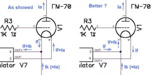
Don't know if it is better, but your suggestion is generally how I do it in my designs, and with GM70s. It does have a pretty significant effect on the level of grid bias required. (Reduces the voltage required at the grid as opposed to the way Rod suggested, enough so that when I built my amps I had to tweak the bias divider/pot ratio to get the voltages into range for the target plate current - I missed it by a pretty significant margin, must have made a mistake in my design analysis or calculations.) EML also recommends the negative terminal of the filament be grounded. (I use the 20AM in one of my designs)
Hi Loren,
Since you are talking about 40W from a pair you can comfortably accomplish this with a pair running in A1 into a 2.5K - 3.5K primary load resistance; the lower end would give you close to 50W and the high end around 40W with significantly lower distortion. Combined plate current could be in the realm of 200mA or above to the dissipation limits of the tubes.
Capacitive coupling would allow you the option of independently adjusting the bias for each tube, with separate filament supplies it would be a simple matter to sample the current in the cathode circuit independently.
I would strongly recommend the Coleman filament regs from the outset because they outperform most unregulated supplies in terms of noise, and perhaps more importantly reduce the cold filament inrush current which with the GM70 takes on ridiculous levels if you don't. (How about >15 - 20A initial inrush depending on transformer winding resistance, rectifier and choke resistances.) I think there is a very real possibility of filament breakage over the service life of these tubes if you don't limit the inrush current somehow. Obviously with 88dB efficient speakers you can tolerate a couple of mV of ripple at the output of the amplifier before it starts to become obnoxious. The regulators need appreciable heat sinking as well which needs to be accounted for up front.
Something to note about the GM70 is that it is cheap which is a good thing, because after 5 years of experience I have concluded they don't last much beyond their rated 1000 hours (maybe + 20%) and need to be changed out in order to maintain decent performance. It's sort of abrupt, and I still don't understand the mechanism after 5 replacement cycles. I should have included hour meters as part of my design.
I use solid state rectification and a CLCLC filter stack comprising 73uF/2H/73uF/2H/90uF, with the final section 40 x 20uF in the PSU and 10uF in the chassis. Well behaved. The chokes have relatively low DCR (<5 ohms) and are placed in the negative rail which sits close to ground which reduces the likelihood of insulation breakdown in the chokes to nil. (old ham trick)
I use stacked 450V 220uF 20% 105C 5000 hour Panasonic electrolytics stacked 3 in series with voltage equalizing resistors. The current equalizing resistors are 120K 5% 3W. The previous set had 171K resistors across them, and over a period of 5 years I had a cap failure - when I investigated I had 2 open equalizing resistors, and 1 cap had failed (close to venting) and 10 others showed signs of distress. I now use resistors rated at 750V with a high pulse rating and 3W rated dissipation. Unfortunately I am not sure how long these will live. The supply voltage is approximately 1025V but varies several % based on line voltage variations.
I have been stacking caps in series for decades and never saw any failures over the 10 - 15yr life of those capacitors (replaced pre-emptively), but I have never triple stacked until this design, nor run at voltages appreciably over 700V from a SS bridge.
That debate seems to rage on �� I had always heard the negative as well, but I believe I remember reading on Rod's pages about why with HIS regulators there was a beneficial reasoning to the positive. Surely I'll be trying both. Maybe negative will be better until a later date when his boards are used? Kevin said when cost not an issue he used LT108x and then Rod board , which is my planned route, so We'lol see how it goes at first with just the LT....
I'm going to post the schematic here in a couple hours when I get back to shop, but first what do you guys do for the heater bridge and heatsinking?
I have a bunch of HFA15TB60 (hexfred) that I wanted to use but was curious about the heatsinking requirements? The HFA's have metal tabs which are live (anode) and so I cannot just bolt them all to the same heatsink. I still don't understand why the heatsinking requirements seem so high in FWB heater designs I see again and again. When making a FWB with 4 individual diodes for an HV supply for example at 400V and 200ma...that's 80W...I can get away without heatsinking the diodes just fine, the heat is dissipated in the components with resistance throught the circuit. So why does every heater design I see, where 20v and 3a (only 60W), where the heat again is dissipated in the filament and/or dropping resistors, say that I need to have them on a big heatsink?
I also have some KBU6M which are good for 6A, and being a plastic case 1 piece FWB would be easy to mount to chassis (remember this chassis is very thick and gives us plenty of heatsink room). But seems silly to use 1000v PIV here, and I'd much rather use the hexfreds...
Just wanted to get that cleared up before I posted schematic...
Thanks all,
Loren
KB2WYL
- Status
- Not open for further replies.
- Home
- Amplifiers
- Tubes / Valves
- Parallel GM70 Amp