Hi,
currently I'm using Deode's DDDAC using parallel PPCM1794 NOS. I'm very pleased from the DAC, but now I'm looking forward - a DSD format 🙂
I saw this thread - TI's DSD1794A
and this one - Parallel DSD1794 NOS/DSD passive I/V
On first look it's exactly what I'm looking for! Unfortunately there is not the whole needed information for me to do this project.
Firts, a schematic would be very helpfull, but even without it we can get a lot information from the pictures. The Arduino scketch isn't look 100% complete, but also gives a basic idea what to do.
So, I'm going to do such a configuration with DSD1794A in 4 parallel DACs, NOS, mono (at least I will try).
For this I need some guidness...
First for me the most interesting is the driver board -
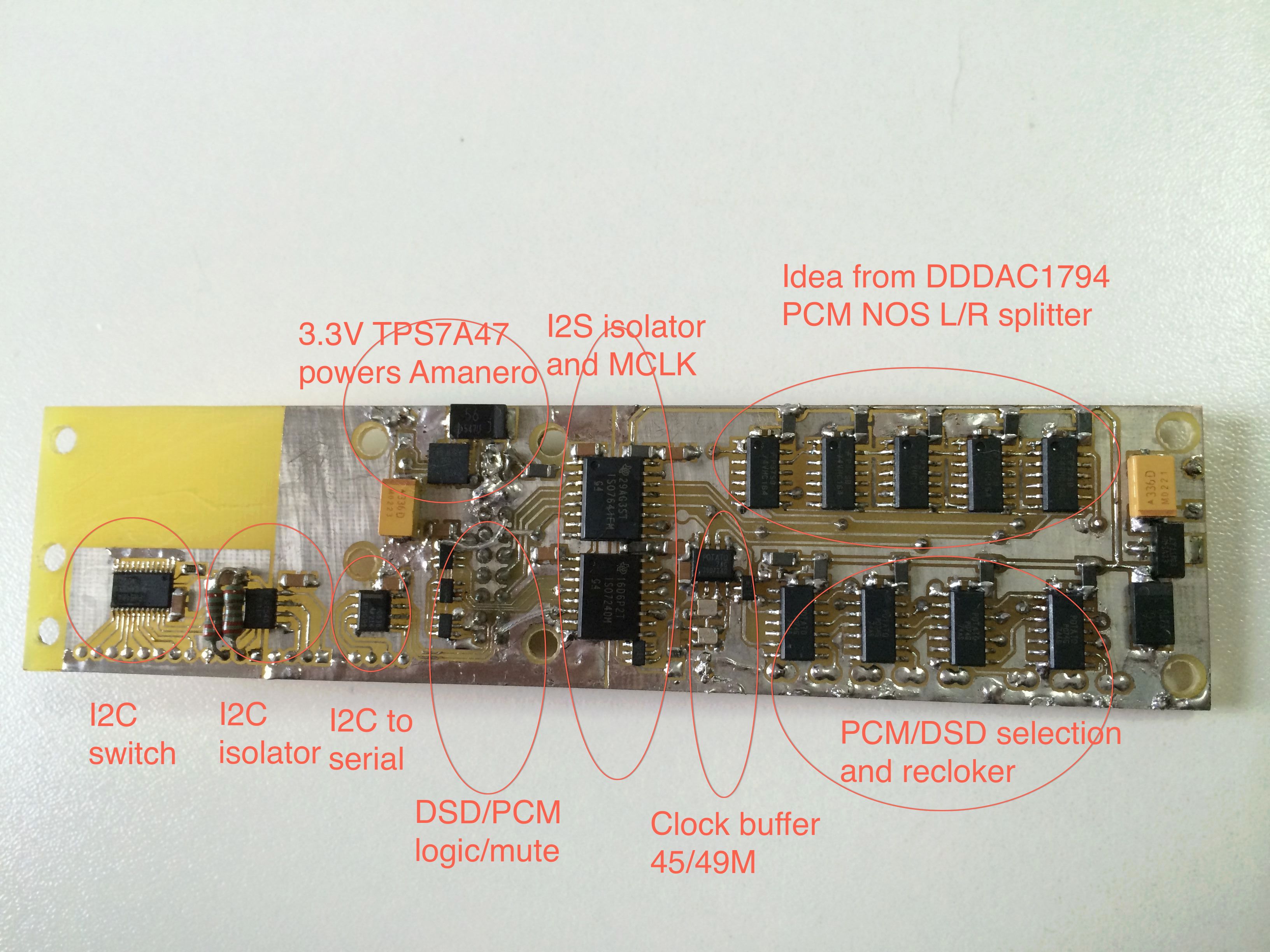
As I saw DSD1794A can be configured in software mode, using I2C. On first look I thouth in this project I2C is used to configure the DSD1794A, but why there is a I2C to Serial converter? Probably the DACs are programmed on SPI interface?
Second - as the DSD1794A is using 2 pins to set the device's address (ADR0, ADR1) only 4 addresses conbinations can be done. To keep the similarity of the DAC's PCBs, I'm going to use only 2 addresses for each channel DSD1794A and a I2C I/O expander. Such as PCF8574, I'm gonna use 4 I2C channels for each DAC PCB. A I2C isolator can be used too (as seen on the picture)
I will not need a clock buffer and a clock divider, because I'm gonna use different USB decoder (XMOS). So this part will be gone in my design.
Here it is some raw schematic of my design, concider the 2 pin headers as s switches controlled by the MCU.
If you see any mistakes in the schematics, the design itself, please feel free to share it here. As I'm not so experinced in DSD mode I need your guidness 🙂
currently I'm using Deode's DDDAC using parallel PPCM1794 NOS. I'm very pleased from the DAC, but now I'm looking forward - a DSD format 🙂
I saw this thread - TI's DSD1794A
and this one - Parallel DSD1794 NOS/DSD passive I/V
On first look it's exactly what I'm looking for! Unfortunately there is not the whole needed information for me to do this project.
Firts, a schematic would be very helpfull, but even without it we can get a lot information from the pictures. The Arduino scketch isn't look 100% complete, but also gives a basic idea what to do.
So, I'm going to do such a configuration with DSD1794A in 4 parallel DACs, NOS, mono (at least I will try).
For this I need some guidness...
First for me the most interesting is the driver board -
As I saw DSD1794A can be configured in software mode, using I2C. On first look I thouth in this project I2C is used to configure the DSD1794A, but why there is a I2C to Serial converter? Probably the DACs are programmed on SPI interface?
Second - as the DSD1794A is using 2 pins to set the device's address (ADR0, ADR1) only 4 addresses conbinations can be done. To keep the similarity of the DAC's PCBs, I'm going to use only 2 addresses for each channel DSD1794A and a I2C I/O expander. Such as PCF8574, I'm gonna use 4 I2C channels for each DAC PCB. A I2C isolator can be used too (as seen on the picture)
I will not need a clock buffer and a clock divider, because I'm gonna use different USB decoder (XMOS). So this part will be gone in my design.
Here it is some raw schematic of my design, concider the 2 pin headers as s switches controlled by the MCU.
If you see any mistakes in the schematics, the design itself, please feel free to share it here. As I'm not so experinced in DSD mode I need your guidness 🙂