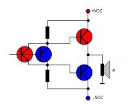
Can it work ? Answer = no 🙂 Either the PNP or the NPN driver can conduct. You cannot cross from one to the other without causing a zone where both output devices will be turned hard on.
this deserves to be explored in a spice sim
it is like putting 2 diodes in series, but not quite the same
if we connect the collectors of input transistors to V+ and V-
we get a typical diamond buffer
I suppose it does not work or does not work well
Because if it did, we surely would see this in amplifiers
I have never seen this before
it is like putting 2 diodes in series, but not quite the same
if we connect the collectors of input transistors to V+ and V-
we get a typical diamond buffer
I suppose it does not work or does not work well
Because if it did, we surely would see this in amplifiers
I have never seen this before
i think i'll try it monday at work.
i want to see if it really makes cross conduction on output stage.
maybe some capacitors will correct the cross conduction problem...
i think about this to correct the low level B distorsion on output.
i saw a similar circuit, but just similar.
i want to see if it really makes cross conduction on output stage.
maybe some capacitors will correct the cross conduction problem...
i think about this to correct the low level B distorsion on output.
i saw a similar circuit, but just similar.
Actually it may work if a means to set the idle current is introduced, and this would most probably be the use of emitter resistors in the output pair.
Something similar is done is some OPamp output stages, except the collectors of the 'drivers'/'bias generators' are tied to the output. This in fact makes them work into the saturation region, but it also presents a form of bootstrap/cascoding.
This indeed does deserve looking at via a spice sim, but what I can tell you right away, is that it transitions towards lower idle currents for every delta (change) of input versus output, so it will probably have a very narrow crossover discontinuity in the middle of the transfer curve. This usually means lots of high order harmonics...
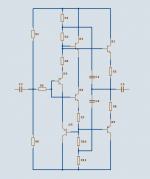
this following i have explored in spice simulation
* cascoding of input pair, with 2 extra transistors, U1-U5, gives a small improvement
* bootstrapping with C1-C4, gives a bigger improvement and reduces 3rd harmonics dist
in a practical circuit i would use resistors+bootstrap, instead of current sources
because it is more simple & because it gives very good result for a buffer application
Attachments
Lumba Ogir said:ilimzn,
long time no see...vacation, maybe?
Beautiful explanation as always.
Thanks LO...
No, just some private matters I had to attend to that took a lot of my time...
Still had no time to try this in a spice sim, but will do so at first oportunity.
- Status
- Not open for further replies.
- Home
- Amplifiers
- Solid State
- parallel complementary stage