I was having a read around cascodes and came across this 1956 thesis paper on cascodes - the interesting point is figure 1b, where it shows a parallel cascode:
https://scholarworks.montana.edu/xmlui/bitstream/handle/1/5007/31762100133923.pdf?sequence=1
Essentially the parallel cascode passes the signal from the anode to the cathode but decouples the path, unlike a anode-cathode serial connection, so that both run in a lower B+ (as a benefit).
I know of the cascode shunt but I thought that this was interesting as I've never seen another 'parallel cascode' so it may be called something else.
If it's useful and doesn't have any draw backs it may help reduce B+ voltages required for cascodes.

NickKUK,
I worked on a 10GHz surface search radar, that had that style of cascode stage for the 30MHz IF amplifier. That cascode's Q is rather high, its bandwidth is much narrower than the 30MHz center frequency.
That cascode works real well for that radar.
But, that kind of cascode circuit is not well suited for Tubes / Valves Hi Fi and Stereo amplifiers that might want to cover from 20Hz to 20kHz;
And not even suitable from 300Hz to 3,000Hz for voice reproduction.
Last edited:
A common-cathode into a grounded-grid circuit is just that - the cascode is a special case of this configuration that saves auxiliary components.
The main benefit of either topology is higher bandwidth, as the Miller effect is avoided. This is of little consequence to audio. The thesis is more interested in other properties such as noise, and is focussed on narrow-band circuits only I think. For wideband such as audio transformer coupling would probably be needed for such a circuit, making the standard cascode much more attractive despite the higher voltage.
The main benefit of either topology is higher bandwidth, as the Miller effect is avoided. This is of little consequence to audio. The thesis is more interested in other properties such as noise, and is focussed on narrow-band circuits only I think. For wideband such as audio transformer coupling would probably be needed for such a circuit, making the standard cascode much more attractive despite the higher voltage.
I read those papers some years ago. Cascodes do work in audio at low level amplification because of their low noise intrinsic capability. The Cascode is not responsible for the Q in a circuit, in RF the Q depends on the value of an inductance or tuned circuit and the resistances or conductance associated with it.
Osvaldo de Banfield,
Agreed.
The resonant LC circuit Q is a function of the Q of the L and Dissipation of the C, and also the driving impedance, and the load impedance that the LC resonator sees.
That special circuit configuration of the cascode in Post # 1, used a resonant circuit.
Audio cascode circuits normally avoid using resonant circuits.
Bandwidth has more than one meaning:
20 to 20kHz is wide bandwidth if you consider the Ratio of the lowest to highest frequency, 1000:1.
Q = 1/1000
But 1 MHz bandwidth at 30MHz center frequency is not wide bandwidth if you consider the ratio of the bandwidth versus the center frequency, 1:30.
Q = 30
Last edited:
Obviously. I had my printed copy since about 5 years in my literature. I tryed cascodes mixed witj van Skoyok phase splitter and a neutralizing mechanism that I had published here. It is a very intersting approach.
But anyway, its a nice paper to practice your circuit calculation capabilities. 😀
Yes sir! Downloaded to a hard drive.
That cct looks like a very ordinary TV or FM front end. Altho sometimes those use a grounded grid as first stage, a better match to a low Z antenna. My thoughts anyway. But an interesting paper tho.🙂
This is not completelly true. A neutralized cascode can match a low z aerial to a high z grid via a tuned tranformer with voltage step up ratio. As the gain in the traffo is almost noise free, the cascode plus traffo gain and s/n are better. Until the design of the guided grid triodes, this topology was extensivelly used in TV tuners.
I was having a read around cascodes and came across this 1956 thesis paper on cascodes - the interesting point is figure 1b, where it shows a parallel cascode:
404
Page not found
We can't find the page you're looking for. The page may have been moved or deleted. You can use the button below to get back to the home page.
THX for the link
What I see is most of a common Toob TV front end. It is parallel only in the schematic.
Both DC supply & the RF signal are in series. The main difference from what was common practice
was the antenna coupling, The first triode was normally connected as grounded grid.
For two reasons. One, the low impedance of the cathode better matches the 75Z impedance of the antenna system.
Second, the grounded grid isolates the input of the first stage from its output.
Lots of equations. But the circuit is not as advertised.
Somebody mentioned not much BW. For TV in North America had to be >6MHz. Is that enough?? 🙂 🙂
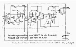
Here is an example of a true cascode FM frontend with ECC85.
It is drawn parallel, and it is parallel connected, DC wise.
But AC wise both triodes are in series cascode.
Hint: the 100pF from plate of 1st triode to cathode of 2nd triode.
Dr1 is a choke ...
It is drawn parallel, and it is parallel connected, DC wise.
But AC wise both triodes are in series cascode.
Hint: the 100pF from plate of 1st triode to cathode of 2nd triode.
Dr1 is a choke ...
Attachments
- Home
- Amplifiers
- Tubes / Valves
- Parallel cascode (1956 thesis)