Does paralleling capacitors to add capacitance change any other parameters. I.e. can I parallel a 10 and 2uF cap to achieve 12 total without other consideration?
Correct. The voltage rating becomes the lowest value.
Ah so if I add a 250v rated cap to a 400v rated one I reduce the overall power handling characteristics?
The amount of voltage that can be safely applied across the capacitors is 250 volts, but that's way more than they will ever see.
Paul
Paul
Ah so if I add a 250v rated cap to a 400v rated one I reduce the overall power handling characteristics?
Thanks pkitt
What voltage ranges are typically seen in passive crossovers? I've read about phase differences between amp and voltage curves in speakers. I assume keeping everything in phase produces the better power response. How do we manipulate this?
What voltage ranges are typically seen in passive crossovers? I've read about phase differences between amp and voltage curves in speakers. I assume keeping everything in phase produces the better power response. How do we manipulate this?
Last edited:
I don't understand the point of the question.I've read about phase differences between amp and voltage curves in speakers. I assume keeping everything in phase produces the better power response. How do we manipulate this?
Assuming you don't make highly resonant filters (generally when making speaker crossovers you don't), the voltage will never be much greater than that produced by the amplifier. If you know how much power your amp produces into a certain impedance load you can work out the peak voltage:What voltage ranges are typically seen in passive crossovers?
Vpeak = 1.414*sqrt(Power*Impedance)
So for an 80Watt into 8ohm amplifier:
Vpeak = 1.414*sqrt(80*8) = 1.414*sqrt(640) = 1.414*25.3 = 35.77V
Going further...
Following TMM's lead, an amplifier delivering 500 watts RMS into an 8-ohm impedance would be generating 63.2 V RMS, or 89.4 volts peak, well below the 250-volt rating of a capacitor.
Paul
Following TMM's lead, an amplifier delivering 500 watts RMS into an 8-ohm impedance would be generating 63.2 V RMS, or 89.4 volts peak, well below the 250-volt rating of a capacitor.
Paul
Jabbejokker,
In another thread, 'badman' commented that two paralleled capacitors have lower esr then one larger cap.
I did some measurements, and at the speaker output I did measure lower distortion.
Upon listening to music, it did sound a little clearer compared to one larger cap.
I now always parallel two caps to make a value.
Mundorfs new EVO winding technology is said to lower esr and esl.
I've tried a lot of capacitors in my designs. The new Mundorf Supreme EVO Silver Gold Oil has displaced my Duelund CAST PIO's as the king of the hill. Yes they are brutally expensive.
Linesource, at AE, which are his new drivers?
Larger value caps have lower ESR too. Assuming we are comparing apples to apples (same series of capacitor = same chemistry, same voltage rating) there should be no difference between say two 10uF in parallel vs one 20uF. Internally the 20uF is effectively just two 10uF in parallel.Jabbejokker,
In another thread, 'badman' commented that two paralleled capacitors have lower esr then one larger cap.
I did some measurements, and at the speaker output I did measure lower distortion.
Upon listening to music, it did sound a little clearer compared to one larger cap.
I now always parallel two caps to make a value.
One advantage of using multiple smaller valued caps is that you have a larger surface area to dissipate heat to the surrounding air, therefore the caps run cooler. A valid consideration for extending the life of electrolytics but pretty much negligible for film caps since their losses are vanishingly low so they don't dissipate much heat at all.
Last edited:
paralleling caps do indeed (sometimes not always) make lower ESR.
this is related mainly to the caps SRF and construction geometry so beyond audio frequencies in most cases.
E.g. narrow lead spacing ( radial dia. ) = higher SRF
but to say "I always parallel caps" is a false conclusion.
also low ESR and low distortion measurements do not follow here.
this is related mainly to the caps SRF and construction geometry so beyond audio frequencies in most cases.
E.g. narrow lead spacing ( radial dia. ) = higher SRF
but to say "I always parallel caps" is a false conclusion.
also low ESR and low distortion measurements do not follow here.
Last edited:
Larger value caps have lower ESR too. Assuming we are comparing apples to apples (same series of capacitor = same chemistry, same voltage rating) there should be no difference between say two 10uF in parallel vs one 20uF. Internally the 20uF is effectively just two 10uF in parallel.
One advantage of using multiple smaller valued caps is that you have a larger surface area to dissipate heat to the surrounding air, therefore the caps run cooler. A valid consideration for extending the life of electrolytics but pretty much negligible for film caps since their losses are vanishingly low so they don't dissipate much heat at all.
And that's why I spend less and less time at this forum.
I said I was going to do something.
Badman said this is what will happen.
I measured using Arta.
Badmans words where validated
Listening tests further proved it.
Along comes TMM.
Question? are we here to help each other? Are we hear to build better speakers than what you can buy elsewhere.
TMM. Do you work for a speaker manufacturer?. Are you trying to prevent us from building great speakers?
Sorry for the negativity.
I measured using Arta.
why not just post your measurements?
perhaps TMM and Badman are both right and youre wrong?
FWIW C.Billy getting personal is not going to help your position.
Last edited:
Measurements and listening show 'Badman' is right.
saying something is so doesn't help anyone.
you said we are all here to help each other right?
TMM has measured crossover distortion and reasonable caps paralleled or otherwise are not the bad guys.
Last edited:
No, i'm an electrical engineer my job is objectifying design decisions like this to work out what is the cheapest/smallest/highest performing configuration of electrical components.And that's why I spend less and less time at this forum.
I said I was going to do something.
Badman said this is what will happen.
I measured using Arta.
Badmans words where validated
Listening tests further proved it.
Along comes TMM.
Question? are we here to help each other? Are we hear to build better speakers than what you can buy elsewhere.
TMM. Do you work for a speaker manufacturer?. Are you trying to prevent us from building great speakers?
Sorry for the negativity.
So lets take an objective look at the topic. Consider this Panasonic FC datasheet (yes, I know it's a polarized capacitor but the technology is fundamentally the same as electrolytic bipolars):
https://industrial.panasonic.com/cdbs/www-data/pdf/RDF0000/ABA0000C606.pdf
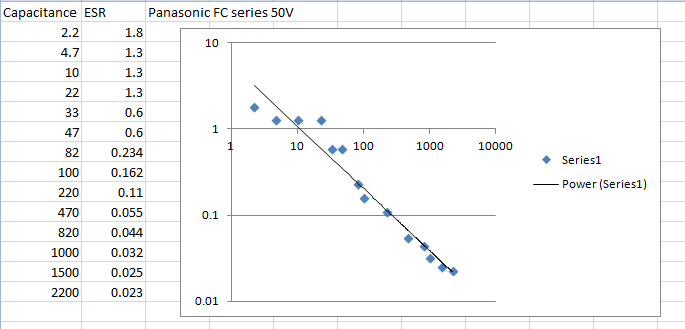
Above I took the data from the 50V capacitors in that datasheet, capacitance and ESR, plotted them and did a line of best fit. As you can see, it fits a power curve, the fitted is y=5.7x^-0.707, y being ESR, x being capacitance. If it were ^-1 it would be inversely proportional (double capacitance, half ESR), being ^-0.707 you do - on average - get slightly lower ESR by using multiple caps but it's not by much. The deviations from the curve are because there are standardised can sizes (4.7uf, 10uf and 22uF are all the same physical size) - either the ESR is directly proportional to the physical size, or Panasonic got lazy and only characterised ESR for each physical size for that particular voltage rating. If this is actually the case or if the 4.7uF's ESR should be a little higher and the 22uF a little lower I have not tested. If they are in fact all the same then it means you need to consider the physical size vs ESR instead of capacitance vs ESR. According to Panasonic's data, if you put two 47uF in parallel (=~100uF) you get 0.3ohms, whereas if you just used the 100uF you get 0.162ohm, significantly lower. The opposite is true for other values so you may need to assess it on a case by case basis.
With regards to distortion, I'm not sure how you manage to measure a difference because in my own testing capacitor distortion is pretty much negligible (<0.01%) compared to speaker driver distortion (>0.1%) for a practical home hifi drivers and listening levels - say a 5-8" woofer and 1" dome tweeter, 1-20Watts. Capacitor distortion only occurs where there is significant voltage dropped across the cap and the speaker is playing at a reasonable volume, which generally only happens in a narrow band of frequencies at the corner frequency of a low/high pass filter. Speaker driver distortion occurs everywhere, so I know which one I worry about more.
Last edited:
- Status
- Not open for further replies.
- Home
- Loudspeakers
- Multi-Way
- Parallel Capacitors