I'm trying to figure out an enclosure for my first build (phono preamp). I think I want to use a 13"x5"x2" Hammond enclosure lengthwise. The below photo is what I have in mind for the rear of the enclosure:

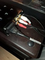
Total area represented is is 2"x5". I initially laid it out without considering a 1/4" inset required for wood sides, so there will need to be a little more squinching things together to make up for that. On the left is the ground post (top), LR-in (middle pair), and LR-out (lower pair). The rest is obvious and/or labeled. The plug is just a hair over 2", so can't be turned sideways. I want the switch to be in the top corner like that for ease of access.
I plan to use shielded cable from a retired pH probe or two from work for the signal. pH probes are extremely sensitive to EMF interference, and I have 2 or 3 dead probes lying around with 10' of cable each, so I figured it was probably as good as I could get (plus it's free). The cable shielding will be grounded. This should help, but I'm not sure it'll be good enough.
I'm a little concerned about the proximity of the signal fixtures and AC power fixtures causing hum issues. I've overestimated things like this before, so figured it'd be worth asking people who have more of a clue. Will this layout be problematic, or am I over thinking it?
If you can find a module which will fit vertically like this one, that would help.
https://sc04.alicdn.com/kf/HTB10FyCeRCw3KVjSZR0q6zcUpXan.jpg_Q55.jpg
If not, I would make the fuse internal, and stack the switch and IEC outlet next to the right side.
Or better, get rid of the IEC and make the cord captive using a restraint where the fuse is now.
https://www.delcity.net/store/Strai...c8mwmg773B1c1UUQe0ns0iZ-kjm8DI04aAl3kEALw_wcB
Last edited:
Does suggesting components that would help mean there will likely actually be a problem? How much air space is enough?
Immediately moving all AC carrying wires to the far side of the enclosure and probably twisting them, while keeping all shielded signal carrying wires in the opposite corner until the last second will buy me ~5.4" of air space for all but the fixtures themselves.
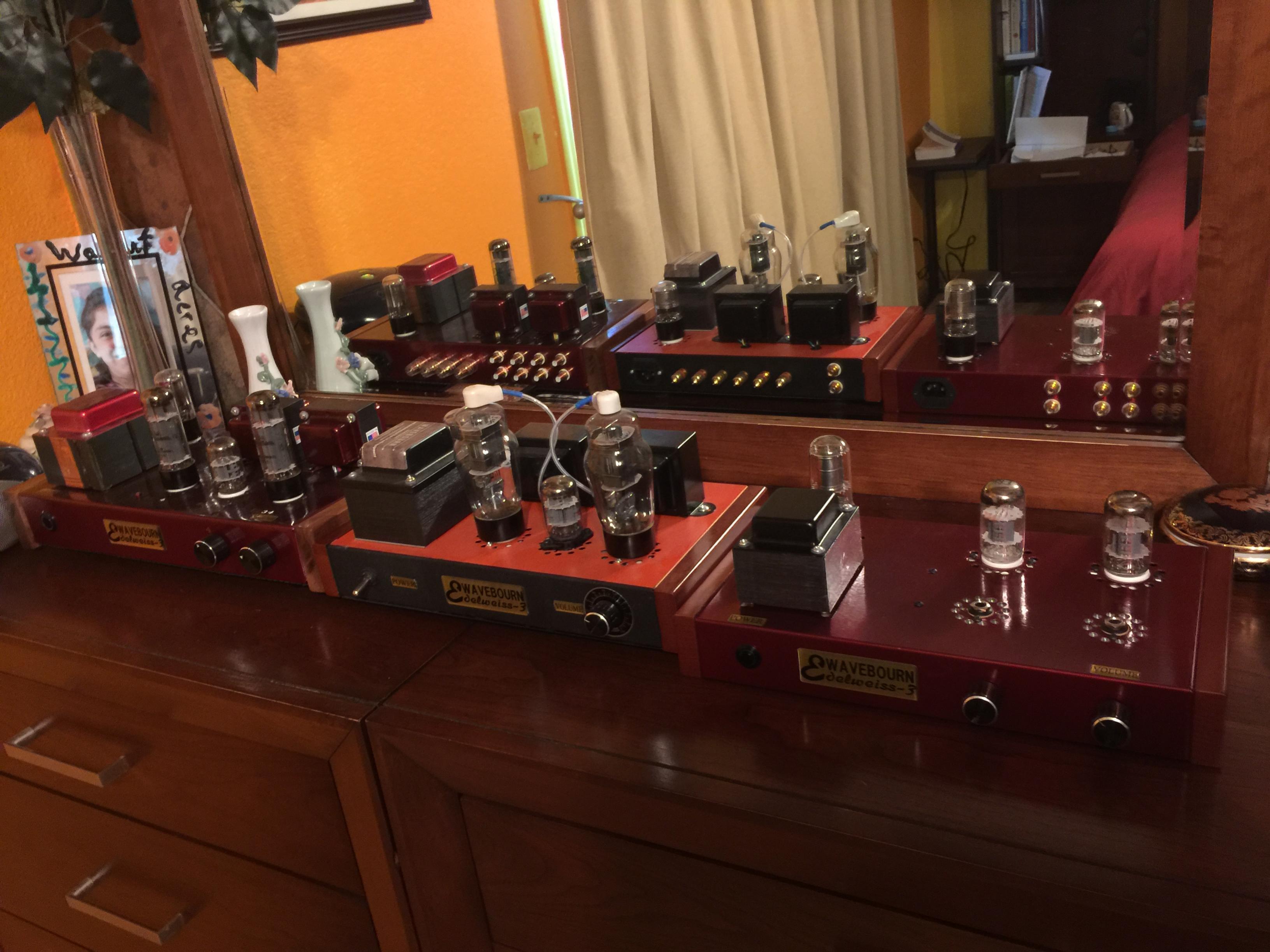
This guy has an IEC immediately adjacent/similarly spaced to what looks to be a signal carrying plug in the center amplifier (see reflection in mirror). Of course, I have no idea about performance or dimensions or anything...
Brainthought: I found that photo looking through the gallery for ideas on component layout vis a vis enclosures. Mayhap I'll do the same to get an idea for acceptable signal/power plug layout.
Immediately moving all AC carrying wires to the far side of the enclosure and probably twisting them, while keeping all shielded signal carrying wires in the opposite corner until the last second will buy me ~5.4" of air space for all but the fixtures themselves.
This guy has an IEC immediately adjacent/similarly spaced to what looks to be a signal carrying plug in the center amplifier (see reflection in mirror). Of course, I have no idea about performance or dimensions or anything...
Brainthought: I found that photo looking through the gallery for ideas on component layout vis a vis enclosures. Mayhap I'll do the same to get an idea for acceptable signal/power plug layout.
The farther apart, the better. It's a phono stage, low signal level and high gain.
Or an external power supply, common these days.
Or an external power supply, common these days.
Right. I get that at a macro level, which is why I'm asking. I do my best to recognize when I don't know something though, and this is one of those instances. Is there a/what is the point of diminishing returns? The EMF isn't infinite.
Cartridge output level = 1mV
AC power line level = 120V
So the noise is a factor of 120,000 larger than the signal, to start with.
Most MM phono stages either have the AC supply external, or at the far other side of a large chassis.
Or batteries. Not to mention MC head amplifiers, which are another factor of 10, or more, lower in level.
That's a speaker output terminal, which is at a high signal level, and at a low impedance level.Does suggesting components that would help mean there will likely actually be a problem? How much air space is enough?
Immediately moving all AC carrying wires to the far side of the enclosure and probably twisting them, while keeping all shielded signal carrying wires in the opposite corner until the last second will buy me ~5.4" of air space for all but the fixtures themselves.
This guy has an IEC immediately adjacent/similarly spaced to what looks to be a signal carrying plug in the center amplifier (see reflection in mirror). Of course, I have no idea about performance or dimensions or anything...
Brainthought: I found that photo looking through the gallery for ideas on component layout vis a vis enclosures. Mayhap I'll do the same to get an idea for acceptable signal/power plug layout.
Very different from a phono input or output.
I get that.... It's an example demonstrating that the relationship is finite. Every phono preamp isn't monoblock or the size of a football field. There are limits to the amount of hum induced by proximity between the signal and power components. I could have just as easily dug out a photo of a preamp tube close to a power transformer. The same relationship applies, and it's finite. What I'm asking, is what are the limits?
Well, everything is finite, but you have to decide what is acceptable.
How about a hum level at -60dB re 10mV in the phono stage output?
That level would still be audible, especially with high efficiency speakers.
You could add an internal shield over the power wiring, board, and components.
Of course all AC leads should be twisted to help cancel the fields.
And even an external AC supply would still result in some measurable hum.
Here's a well-designed MC/MM phono stage. About the best you can do in a single chassis design.
https://www.stereophile.com/images/1011para.inside.jpg
Another more typical single chassis phono preamp.
https://www.analogplanet.com/images/12020LIB.jpg
Last edited:
Given that this is your first project, you will likely save yourself a lot of grief by using an external power supply. This also gives you the flexibility to try another phono preamp design and compare the two.
My impression is that the panel layout looks way too crowded, and the AC power far too close to the phono inputs.
My impression is that the panel layout looks way too crowded, and the AC power far too close to the phono inputs.
Everything is already set in stone except the enclosure.
How far is typically far enough to not have any noticeable hum from this specific source at nominal volume levels?
How far is typically far enough to not have any noticeable hum from this specific source at nominal volume levels?
That would be empirical data, dependent on many details of your implementation,
as well as the other components in your system. The cartridge impedance and cables
can also affect the sensitivity to noise pickup.
Most would characterize it by voltage amplitude at the phono jack outputs with a specific
input termination. In practice it is combined with the wideband noise, in a (s + n)/n spec
at a particular output signal level, typically 10mV for MM.
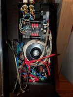
This is built around the VSPS (very simple phono stage) from Phonoclone. I wrapped the Trafo and signal wires with Faraday tape, it's compact, actually tight inside, and has zero hum, dead silent. Chassis is 8x4x2 inches.
Attachments
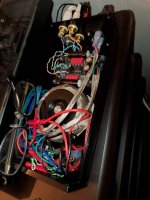
So the power transformer is right next to the phono pcb? Don't think I would have made that choice,
no matter what kind of shielding is used. However, depending on the tape and details of how it is used
on the transformer, a shorted turn could have been formed.
no matter what kind of shielding is used. However, depending on the tape and details of how it is used
on the transformer, a shorted turn could have been formed.
Dead silent, clean and clear. Not the end all of phono stages of course, just an easy, cheap, and quick one! ZERO hum!
More information please! I have 4.5"x2" to play with, and it looks like you have all the plugs on the skinny end, which would give you 1" sq. less room than I'm considering. Photo of the business end? Topside?This is built around the VSPS (very simple phono stage) from Phonoclone. I wrapped the Trafo and signal wires with Faraday tape, it's compact, actually tight inside, and has zero hum, dead silent. Chassis is 8x4x2 inches.
This faraday tape?
Do a search for Faraday tape or mu metal tape, the stuff i bought from Am*z*n is a metal thread woven fabric, with a backing that needs to be peeled off. Not the most fun to work with. Rayma is correct though, cramming the trafo right next to the board wasn't the wisest choice, but it's the one I made, because I wanted it compact, and I got away with it. Of course it may be that the VSPS is pretty stable and forgiving. Many will build the psu in a separate chassis with an umbilical cord, more work, another chassis, but it elevates your chances of success (no hums). Be careful, good luck, and have fun.
Attachments

- Home
- Amplifiers
- Tubes / Valves
- Panel layout Q