I have a Panasonic RAMSA 9110e amplifier that came into my possesion some time ago. As far as I can tell channel B functions normally. Channel A however does not. When channel A is connected to a speaker there is noise. Sounds kind of like white noise, but grainy and not quite as dense in nature if that makes sense. Unfortunately I don't have an oscilloscope to see the waveform of it.
I found a video where somebody else had a Ramsa with a channel A problem. Turned out that corrosive glue had done a number on a component or two.
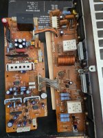
Like the Ramsa in the video mine also had glue that didn’t look all that great so I pulled the 3 caps with glue under them. Came out real easy. 😅

I've cleaned off the glue now. Some of the glue was on diode legs so I checked the diodes with a multi-meter, but they were fine.
While I was at it I checked the 3 caps that I pulled and they read C120 - 460uf (100V, 470uf spec.), C121 - 460uf (100V, 470uf spec.) and C116 - 550uf(10V, 470uf spec.). The first two are pretty close to spec. Not sure what to think about the 10V one. 470 * 1.2 = 564. I suppose if it is a part with a +/-20% or so manufacturing tolerance and serves it’s purpose in the circuit then it’s fine too. But what is the manufacturing tolerance of an electrolytic capacitor anyway? I googled that and apparently it is typically 20% (source). Same source says that capacitance drifts over time. Would you change this cap for one closer to spec?
Small components around big caps with the glue aside what looked suspect was IC101 - MC-8134.

It’s outer shell had some crystals on it. I cleaned them off with some toilet paper and now it visually looks the same as the IC below it. No holes on it, but the crystals must have come from the inside of it?
I’ve turned the amplifier on and played some music with it 2 times before disassembly:
1)The first time the noise disappeared for a while and then reappeared when I turned it up.
2)The second time the noise was there from the start and followed the level of how high I turned up the amp.
If the noise gets amplified based on how high up the amplifier is turned, then it must be coming from somewhere early in the signal path before attenuation. Thinking this I traced the early signal path from signal input to attenuation.

And what do you know? IC101 or MC8134 sits between the two. (page 31, service manual WP9110c, download link) Haven't seen a difference between the WP9110e I have and the WP9110c service manual yet, btw.
I’ve not seen a part like this before and have only some basic knowledge of how some of the stuff in electronics works. Would you think that IC101 is probably damaged? What was that crystal formation on it? What happened to it?
I wasn’t able to find information on what MC-8134 does so I turned to my last resort - ChatGPT. This was the answer I got: “It functions as a voltage-controlled amplifier (VCA), which allows for adjustable gain control in audio signal paths. This IC is typically employed to manage audio signal levels dynamically, providing features such as automatic volume adjustments, noise gating, or signal mixing in professional audio equipment.” ChatGTP couldn't provide a source, said something like answer derived from general knowledge, but it seems like it might be an accurate one.
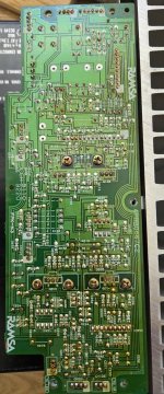
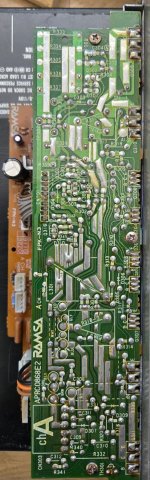
Not much else jumps out at me on these boards. There is some brown stuff on the undersides of the boards - old flux residue? (see the 3 images attached to this post) If not IC101 what else could be the culprit?
I found a video where somebody else had a Ramsa with a channel A problem. Turned out that corrosive glue had done a number on a component or two.
Like the Ramsa in the video mine also had glue that didn’t look all that great so I pulled the 3 caps with glue under them. Came out real easy. 😅
I've cleaned off the glue now. Some of the glue was on diode legs so I checked the diodes with a multi-meter, but they were fine.
While I was at it I checked the 3 caps that I pulled and they read C120 - 460uf (100V, 470uf spec.), C121 - 460uf (100V, 470uf spec.) and C116 - 550uf(10V, 470uf spec.). The first two are pretty close to spec. Not sure what to think about the 10V one. 470 * 1.2 = 564. I suppose if it is a part with a +/-20% or so manufacturing tolerance and serves it’s purpose in the circuit then it’s fine too. But what is the manufacturing tolerance of an electrolytic capacitor anyway? I googled that and apparently it is typically 20% (source). Same source says that capacitance drifts over time. Would you change this cap for one closer to spec?
Small components around big caps with the glue aside what looked suspect was IC101 - MC-8134.
It’s outer shell had some crystals on it. I cleaned them off with some toilet paper and now it visually looks the same as the IC below it. No holes on it, but the crystals must have come from the inside of it?
I’ve turned the amplifier on and played some music with it 2 times before disassembly:
1)The first time the noise disappeared for a while and then reappeared when I turned it up.
2)The second time the noise was there from the start and followed the level of how high I turned up the amp.
If the noise gets amplified based on how high up the amplifier is turned, then it must be coming from somewhere early in the signal path before attenuation. Thinking this I traced the early signal path from signal input to attenuation.
And what do you know? IC101 or MC8134 sits between the two. (page 31, service manual WP9110c, download link) Haven't seen a difference between the WP9110e I have and the WP9110c service manual yet, btw.
I’ve not seen a part like this before and have only some basic knowledge of how some of the stuff in electronics works. Would you think that IC101 is probably damaged? What was that crystal formation on it? What happened to it?
I wasn’t able to find information on what MC-8134 does so I turned to my last resort - ChatGPT. This was the answer I got: “It functions as a voltage-controlled amplifier (VCA), which allows for adjustable gain control in audio signal paths. This IC is typically employed to manage audio signal levels dynamically, providing features such as automatic volume adjustments, noise gating, or signal mixing in professional audio equipment.” ChatGTP couldn't provide a source, said something like answer derived from general knowledge, but it seems like it might be an accurate one.
Not much else jumps out at me on these boards. There is some brown stuff on the undersides of the boards - old flux residue? (see the 3 images attached to this post) If not IC101 what else could be the culprit?
Attachments
Last edited:
Hey !
About capacitors : the ESR (equivalent serie resistor) is changing sometimes as the cap ages, so it could fool the multimeter in augmenting the value. The liquid inside dries, so it can reduce the value. At the end, with a simple capacitance meter, testing the cap is a bit random ! You would need further testing equipment to really conclude about their present state. In your case, I don't think they are the cause of the problem, but changing them by new ones will do no harm. It's a weak component on amplifiers.
About the MC8134 : if I understand, it takes the two polarities of the balanced signal and substract them to give the output. I don't find any information about the chip neither on internet. It is likely the culprit as you said in my opinion
Now : If we admit that MC8134 is indeed faulty, there are four solutions : salvage the chip in an other broken equipment and put it here, find a modern replacement, order the chip from Utsource (a really bad idea because notoriously known for scam people desperately looking for an old part so don't do this !), and finally rebuilding an equivalent chip from discrete components.
About building the new chip / finding a modern replacement : this is the way to go in my opinion.
1) You would need to know how the chip works : I can see inputs (4,5), output (7), GND (6), and power supplies (1, 2, 3, 8, 9, 10). I do not have the feeling that one pin is an input to set the gain, as ChatGPT suggested by using the term VCA (voltage controlled amplifier). I think the chip is simply making the difference of the two input signals. Once again, having a scope would be useful to really test its behaviour !
2) If we admit the chip is simply doing the difference between the signals, then I think that it would be easy to replace it with a modern one. Find a chip with roughly the same power supply range, hook it up in the PCB and you're good !
So, IF we suppose the noise is coming from MC8134 and IF we take for granted that its behaviour is simply to differentiate the input signal, THEN finding a replacement is easy as I'm sure plenty of chip can do this. something like this MAX97220A (https://www.analog.com/media/en/technical-documentation/data-sheets/max97220a-max97220e.pdf) is what I have in mind. You would have to look for power supply range, output impedance, etc, but I think a lot of modern will fit as having good specs compared to old chip !
PS : Having a scope is really a must have in audio repair so I guess if you are going to do other one, just find one ! Even a cheap one will of 50MHz will do for some quick debug
@degleve Hey to you too and thanks for the input!
According to the amplifier block diagram there isn't amplification before attenuation, but at the same time it looks pretty clear from the Driver A circuit board diagram that MC-8134 makes one signal out of two and there is a variable resistor(VR101 for DC offset adjustment) on the -18V rail going to IC101/MC8134 from IC102/MC5707 so MC8134 must be the differential amplifier in the block diagram.

I stumbled upon the pin-out of IC8134. Apparently it was at the bottom of page 21 of the manual. Pin 6 is indeed ground, like you said, degleve. I had been wandering what it was. The IC appears to be a dual stage device. Stage 1 looks to be powered by the +/-35 rails and stage 2 by the +/-18V rails.

On the back of the amplifier it says +4db 40kohm input and there is one 10kohm resistor on both the cold and hot signal in before MC-8134. Says on top cover that 0dB is referenced to 0.775V RMS - not sure if that's relevant or not. Maybe MAX9722C is a good fit. That package may not be nice to solder though.😅 Could an IC like MAX9722A or E work with a voltage regulator +/- 18 to +/-5V? I haven't actually seen a chip yet that had 6 supply lines. Some would have to be left unconnected or do they need to go to ground after a resistor?🤔 Another question is if the +4 dB 40k input spec. means that MC-8134 has 4db gain. Maybe that is what stage 1 on it does. 🤔

INA137 from TI has +/- 18V supply voltage spec. and package has legs. 🙂 Not sure if it's a good fit based on other specs, but it's late and I've been looking at this for hours now.
According to the amplifier block diagram there isn't amplification before attenuation, but at the same time it looks pretty clear from the Driver A circuit board diagram that MC-8134 makes one signal out of two and there is a variable resistor(VR101 for DC offset adjustment) on the -18V rail going to IC101/MC8134 from IC102/MC5707 so MC8134 must be the differential amplifier in the block diagram.
I stumbled upon the pin-out of IC8134. Apparently it was at the bottom of page 21 of the manual. Pin 6 is indeed ground, like you said, degleve. I had been wandering what it was. The IC appears to be a dual stage device. Stage 1 looks to be powered by the +/-35 rails and stage 2 by the +/-18V rails.
On the back of the amplifier it says +4db 40kohm input and there is one 10kohm resistor on both the cold and hot signal in before MC-8134. Says on top cover that 0dB is referenced to 0.775V RMS - not sure if that's relevant or not. Maybe MAX9722C is a good fit. That package may not be nice to solder though.😅 Could an IC like MAX9722A or E work with a voltage regulator +/- 18 to +/-5V? I haven't actually seen a chip yet that had 6 supply lines. Some would have to be left unconnected or do they need to go to ground after a resistor?🤔 Another question is if the +4 dB 40k input spec. means that MC-8134 has 4db gain. Maybe that is what stage 1 on it does. 🤔
INA137 from TI has +/- 18V supply voltage spec. and package has legs. 🙂 Not sure if it's a good fit based on other specs, but it's late and I've been looking at this for hours now.
Nice found for the page 21 !
About the GND : it's just for the chip to have some reference voltage to work with (providing just positive and negative supply is not reliable as they can vary so your middle point vary as well)
About the +4dB / 40kOhm : 40k is the input impedance of the differential amplifier in my opinion. The spec states it as "balanced input impedance" at the beginning of the manual ! So on this, just take a replacement with same value or higher (input impedance means how much the differential amplifier can perturbates your input signal, so the higher the better !). +4dB is indeed the gain I think.
About the +0dB reference : I don't understand what it means ! Not quite good with the theory of differential amplifier and how the specify gains. By curiosity, could you measure the output of the chip on a working channel (is there one ?) to see if the steady state offset is 0V or something else ? (I guess 0V but just to be sure). In any case, the output of the differential amplifier is AC coupled so it does not matter that much.
About serie resistors : I guess they are just here to prevent too much current flowing through the input. Just let them, they won't have effect in the input in my opinion here
About the package : Of course, find a replacement that you feel confortable to solder after, I'm sure you will have some choice. The digikey search tool for component is quite nice (even if a bit chaotic at first) so you may maybe use it to find a replacment (you can there specify voltage out, number of channels, package, etc).
About the replacement voltage range : you can either find a chip to do a regulation (could be more power efficient but you have to add more components and set up the regulator properly), or you can just use a voltage divider with resistors to power the replacement chip.
Just look how much current the chip will draw and make sure the current flowing through your voltage divider is ten times that ! (this is for the chip not to change the value you made with your voltage divider when it will begin to draw current from it to function - this is just making the output impedance of the voltage divider smaller than the input impedance of the chip power supply). It is a bit less efficient in terms of power consumption (but here it will reallly does nothing as some mA will flow through high values resistors). Make sure to make the divider from the lower voltage rail you get so you waste less current in dropping the voltage.
About the replacement : I think the old chip had numerous power supply rails because of some difficulties at the time to make some efficient chip ? It would be nice to have the point of view of someone acquainted with IC history and common practice at the time (the amp date from the 90s I see on internet). In any case, I'm sure you can find a differential amplifier with 3 power pins (+V, -V, GND) and 3 pins per amplifier channel on the chip (Cold, Hot, Out). If more channel, just check the datasheet about how to tie them. It is better to avoid power consumptions problem or floating pins to get up some noises and perturbate the chip !
The TI you mentioned seems nice ! Do you know voltage range of the input in your amp, to be sure its within spec of it ?
Also, input impedance is a bit less but I guess it is really no problem here, since you have series resistors & your source is probably really low impedance so no worry🙂
Apparently I have the Ramsa WP-9110C not WP-9110e, says WP-9110C on the back of it. Not sure where I got the letter e from. There probably isn't even a WP-9110e. 😅
The amp is from the 80s even. I found an article dated February, 1987 about Ramsa WP9110 and 9220.
I put 0.775V RMS and a voltage gain of 1 in this calculator with waveform = sine-wave selected and it gave me a peak voltage of 1.0960155108391487. I put that long number and output voltage of 24.5 in this other calculator and it gave me a result of 26.98698768 or ~27dB gain. I don't know if it works this way that you take the peak voltage of a sine wave and use that to calculate the gain, but the Ramsa WP9110C manual states that it's supposed to achieve it's rated output of 24.5V @ 150W into 4ohm load with a 20khz sine wave playing when checking it's power output/THD. (page 11 of the manual)
I googled what the difference between dB and dBu is. And Google now apparently also gives AI answers and this was it:
dBu (Decibels relative to 0.775 Volts):
That article from 1987 states that: "With the control at '0' (set fully clockwise), the unit should reach its rated output when a +4dB input level is reached."
So 40kohm +4db input means that the range is 0 to ~1.228V RMS, but then the MC-8134 has a gain of -4dB? 🤔. INA137 can also be had with -6db gain. There is also something like THAT 1256P08-U with a gain of -6dB. If the chip has less gain than the original all it means is that the amp will need more input input voltage before it reaches maximum power/clips doesn't it? I could replace MC-8134 on both channels to have it match if the fix works.
As far as I can tell, Channel B is operational - there wasn't any grainy sound. MC-8134 is in a pretty bad place to measure, but potentially if I soldered a wire on its leg it's output could be measured. Requires me to get board B out to solder though. But, lol, the MC-8134 on B board also has crystals on it, I just looked to see about measuring. Maybe it hasn't degraded enough to cause problems on board B yet. An oscilloscope would help a lot if I had one to determine if it really is the culprit on board A. Could still be a bad cap somewhere or something else, I haven't checked all of them.
Does "steady state offset 0V" mean that with an input of 0V to the chip it should have 0V output?
The amp is from the 80s even. I found an article dated February, 1987 about Ramsa WP9110 and 9220.
I put 0.775V RMS and a voltage gain of 1 in this calculator with waveform = sine-wave selected and it gave me a peak voltage of 1.0960155108391487. I put that long number and output voltage of 24.5 in this other calculator and it gave me a result of 26.98698768 or ~27dB gain. I don't know if it works this way that you take the peak voltage of a sine wave and use that to calculate the gain, but the Ramsa WP9110C manual states that it's supposed to achieve it's rated output of 24.5V @ 150W into 4ohm load with a 20khz sine wave playing when checking it's power output/THD. (page 11 of the manual)
I googled what the difference between dB and dBu is. And Google now apparently also gives AI answers and this was it:
dBu (Decibels relative to 0.775 Volts):
- dBu is a decibel unit that measures voltage, with a reference voltage of 0.775 Volts.
- 0 dBu represents a voltage level of 0.775 Volts.
That article from 1987 states that: "With the control at '0' (set fully clockwise), the unit should reach its rated output when a +4dB input level is reached."
So 40kohm +4db input means that the range is 0 to ~1.228V RMS, but then the MC-8134 has a gain of -4dB? 🤔. INA137 can also be had with -6db gain. There is also something like THAT 1256P08-U with a gain of -6dB. If the chip has less gain than the original all it means is that the amp will need more input input voltage before it reaches maximum power/clips doesn't it? I could replace MC-8134 on both channels to have it match if the fix works.
As far as I can tell, Channel B is operational - there wasn't any grainy sound. MC-8134 is in a pretty bad place to measure, but potentially if I soldered a wire on its leg it's output could be measured. Requires me to get board B out to solder though. But, lol, the MC-8134 on B board also has crystals on it, I just looked to see about measuring. Maybe it hasn't degraded enough to cause problems on board B yet. An oscilloscope would help a lot if I had one to determine if it really is the culprit on board A. Could still be a bad cap somewhere or something else, I haven't checked all of them.
Does "steady state offset 0V" mean that with an input of 0V to the chip it should have 0V output?
Last edited:
About dB, dBu : just a little explanation : the decibel is just a way to compare two numbers. They are a lot of different "dB" scale. What is in common with all these dB scales is that they all take a reference point, and tell you how far from it you are. So, in a dB scale (let's take dBu for example), the reference point is 0.7V. From this, any voltage higher than 0.7V will be associated with a positive dBu value on this scale, and any voltage with a smaller value will be associated with a negative dBu voltage. Finally, the same value is associated with 0dBu.
But you really have to understand that speaking of dB without specifying a reference point (unlike what we've done by adding a "u" after dB) have no sense !
To be complete, the formula used to compute the dB value is here : dB_value = 20*log( value / value_of_reference). You see from it that with no value_of_reference define, impossible to compute anything.
About your computing : I understand what you are trying to do here, but I do not know if you will be successfull trying to compute some precise range with so little precise and clear technical data at your disposal. However, the differential chip tell you that it got a +4dB gain (you made it -4dB, I do not know why ?). So I guess you just have to find a replacement not so far and as you said replace both channel 🙂
About being sure of this : to be really sure of this, the best would be to send a sine on the working channel, and to check the amplitude after the MC8134. Even with no proper scope and signal generator, you can maybe do it. I guess you have a source to send to the amplifier. So just go on youtube and type 1000 Hz sine wave and play it through the amplifier. To measure the amplitude, you can use the multimeter. You surely have on it a AC option when measuring voltage. This will give you either the amplitude or the RMS value of the sine. Finally, just give us the input and output value and we will be able to see how much gain the chip has performed ! So we do not rely on some marking on the chip, but we are sure of which gain we are looking for !
I calculated that if the input signal was 0.775 + 4dbu the amplifier would have a gain of something other than 27 as described in the manual, but if I put in exactly 0.775 then the calculated gain was 26.98698768 (or ~27). Thus I figured if the max input is 0.775 + 4dbu, then the gain of MC8134 should be -4db to account for the discrepancy. I could be wrong about the gain of -4 on MC8134.
In any case I should have an oscilloscope on loan next week to check the signal before and after it goes through MC8134. This should show if the MC8134 in question is producing noise and what gain that MC8134 has.
In any case I should have an oscilloscope on loan next week to check the signal before and after it goes through MC8134. This should show if the MC8134 in question is producing noise and what gain that MC8134 has.
Last edited:
- Home
- Amplifiers
- Solid State
- Panasonic RAMSA WP9110e repair