Hi,
I have built up the P88 preamp.
http://sound.westhost.com/project88.htm
I'm using a 100K Ladder type Step Attenuator.
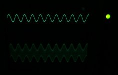
The issue I'm having is when I turn the step attentuator
to -33dB(which is 100K and 2.2K), the output goes into oscillation.
It does this for the next few steps and then goes back to normal.
This is with a 1VP-P sine wave on the input.
The other levels are just fine on the step attenuator until I reach the 100K/2.2K. I have double checked and measured the step attentuator, all values are correct.
In the P88 notes, it mentions if you set the P88 2nd stage to 0dB, it may oscillate. I have the switch set to 1 On, 3-4OFF, which should be 4.44dB for both channels.
Should the Op amp be slightly warm to the touch?
Any ideas?
Thanks.
I have built up the P88 preamp.
http://sound.westhost.com/project88.htm
I'm using a 100K Ladder type Step Attenuator.
The issue I'm having is when I turn the step attentuator
to -33dB(which is 100K and 2.2K), the output goes into oscillation.
It does this for the next few steps and then goes back to normal.
This is with a 1VP-P sine wave on the input.
The other levels are just fine on the step attenuator until I reach the 100K/2.2K. I have double checked and measured the step attentuator, all values are correct.
In the P88 notes, it mentions if you set the P88 2nd stage to 0dB, it may oscillate. I have the switch set to 1 On, 3-4OFF, which should be 4.44dB for both channels.
Should the Op amp be slightly warm to the touch?
Any ideas?
Thanks.
Hi,
how/where have you coupled the attenuator?
Before the amp or after the amp?
Or is there a way to tap into the PCB between the two active stages?
how/where have you coupled the attenuator?
Before the amp or after the amp?
Or is there a way to tap into the PCB between the two active stages?
Bengali said:Hi,
I have built up the P88 preamp.
http://sound.westhost.com/project88.htm
I'm using a 100K Ladder type Step Attenuator.
The issue I'm having is when I turn the step attentuator
to -33dB(which is 100K and 2.2K), the output goes into oscillation.
It does this for the next few steps and then goes back to normal.
This is with a 1VP-P sine wave on the input.
The other levels are just fine on the step attenuator until I reach the 100K/2.2K. I have double checked and measured the step attentuator, all values are correct.
In the P88 notes, it mentions if you set the P88 2nd stage to 0dB, it may oscillate. I have the switch set to 1 On, 3-4OFF, which should be 4.44dB for both channels.
Should the Op amp be slightly warm to the touch?
Any ideas?
Thanks.
Any idea why the op-amp stages have DC gain as well as AC gain ?
Any audio ccts I have seen usually have a cap between the inverting input feedback resistor and ground.
Re: Re: P88 Preamp Issue
Any DC offset from the first stage will be amplified and you could end up with a serious offset.
nigelwright7557 said:
Any idea why the op-amp stages have DC gain as well as AC gain ?
Any audio ccts I have seen usually have a cap between the inverting input feedback resistor and ground.
Any DC offset from the first stage will be amplified and you could end up with a serious offset.
Hi,
are two of the switches 1 to 4 always closed?
Each active stage becomes an opamp follower (gain 0dB) if the feedback switch is open.
I don't like that. What happens to your oscillation if you change the switch positions?
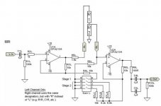
I'm guessing that R5 & R6 are remnants from the linear pots ESP used.
If you have a logarithmic attenuator then R6 can be open circuit or 100k. 100k pot feeding Zin=15k is not usually recommended.
R5 could be much lower, maybe 100r like the second stage.
There appears to be no RF filtering at any of the inputs.
are two of the switches 1 to 4 always closed?
Each active stage becomes an opamp follower (gain 0dB) if the feedback switch is open.
I don't like that. What happens to your oscillation if you change the switch positions?
I'm guessing that R5 & R6 are remnants from the linear pots ESP used.
If you have a logarithmic attenuator then R6 can be open circuit or 100k. 100k pot feeding Zin=15k is not usually recommended.
R5 could be much lower, maybe 100r like the second stage.
There appears to be no RF filtering at any of the inputs.
Hi Andrew,
If I have both switch #1 and 4 closed, it stops osciallating.
It has an issue when only sw#1 is closed.
Right now, I have R5 as 100ohms.
I'm using a 100K Ladder Step Attenuator, looks like the values are for log.
Should I leave R6 open or 100K? What is affected by doing either?
Right now R6 is 15K per the original circuit.
Is it critical to get the rail voltages to match? I measure +15v and -14.8v.
Thanks!
Bengali said:I will increase the 2nd stage gain and see if it goes away.
The step attenuator is between the stages. The pic shown is how I have it wired. It is cap coupled.
Thanks 🙂
You see R2L, 1k, in your diagram,.
This resistor should be as close as possible to PIN 3.
Now, also PIN 2 can need a Gate Stopper resistor, ~ 1 kOhm.
So my advice:
Put one 1K resistor, as close as possible to PIN2.
That is from junction R3L/R4L to Pin2 of the OPA2134.
High input impedance Op-Amps, often needs these Gate Stoppers,
as they have JFET transistors as input devices.
By the way, Same goes for PowerAmplifier MOSFET, HEXFET in output stages.
These resistors should also be as close as possible to GATE.
Lineup 🙂 regars
R6 is only required for linear pots for the fake law thingy.
I've been told by some to leave them out or by others to add a different value. Do a search of the ESP forum on R6 as there's plenty of info on it there.
http://sound.westhost.com/phpBB2/
In the P88 build notes, it recommends SW4 to remain closed for high speed opamps and there's a note to add a small cap (22pF) in parallel with R3L and R3R to help to prevent oscillation.
leaving switches 2, 3 and 4 open converts the second stage to unity gain.Bengali said:Hi Andrew,
If I have both switch #1 and 4 closed, it stops osciallating.
It has an issue when only sw#1 is closed.
This brings the opamp to it's least stable state and it looks like the PCB has affected this stability to the point of oscillation.
Bad design or bad PCB.
Wire a 10k permanently across the switch position and keep the switches for increasing the gain above the +6db setting of the permanent 10k.
Hi Andrew, while I was still learning I made one of those preamps by drawing the pcb with a black marker... I.e.... not very nice...
But I think my layout was pretty tight (very similar to proven cmoy)... anyway I had no problems with the boards... even used opa2777 and 8 ( one is unity stable- marginaly), as well as the opa2132 or 34 .
I think if you like the sound so far, it would be prudent to order the boards from Rod...
I love the volume and pan control... I have been copying the p88's shamelessly since I tried it the first time...
thanks everyone for your help.
btw, I am using Rod's pcb. As long as I have SW#4 closed, it's okay. I will also try the 1K on pin 2.
btw, I am using Rod's pcb. As long as I have SW#4 closed, it's okay. I will also try the 1K on pin 2.
presumably it's OK if switch 2 or 3 are closed instead of switch 4? check it.Bengali said:I am using Rod's pcb. As long as I have SW#4 closed, it's okay. I will also try the 1K on pin 2.
Is the opamp soldered in or socketed?
Try other dual, unity gain stable opamps. they may be OK in this topology. But do make sure each other opamp is properly decoupled otherwise you enter a lottery. which reminds me. Could further attention to decoupling solve the 2134 oscillation problem?
If after all your experimentation you find no solution then solder a resistor across one of the switches. How high can that resistor be and stay stable? 20K 30K? 51k? try it.
Hi Andrew,
it's stable now, with the other dip switch setting closed.
I'm having an issue with the step attenuator. It's a 100K 24step Ladder attenuator kit from HK.
Here are some of the resistor values that it uses:
Step# R1 R2
01 100K Short
02 100K 39R -67dB
03 100K 100R -58dB
04 100K 270R -50dB
Input is 1Khz Sine 1Vp-p. When I have it on the 1st position, I get 0volts on the output which is correct. However, when turn the step att. to Step 2, I get 1Vp-p on the output and it goes on up from there as I turn the step att.
I should be getting milivolt, not jump from 0v to 1V within the first
2 steps. Does not matter what the gain switch settings are.
R5 is 100ohms and R6 is now 100K
Any ideas?
Thanks again everyone 🙂
- Status
- Not open for further replies.
- Home
- Amplifiers
- Solid State
- P88 Preamp Issue