That is not what the Zobel is intended to do.There is no point to use zobel or patches and medicine to cure oscillation or instability you need to find out where is it coming from and kill it at birth not after.
It is a load where no other load exists and that load is only there at High Frequency (HF).
As such it helps to control the amplifier gain @ HF, where without that HF load the gain of the amplifier can change.
It's the control of the HF gain that provides what the amplifier needs.
P3As ready for testing. Thank abetir by its pcb design, very very compact.
An externally hosted image should be here but it was not working when we last tested it.
An externally hosted image should be here but it was not working when we last tested it.


Salvaged OTs from old Gradiente 366???P3As ready for testing. Thank abetir by its pcb design, very very compact.
An externally hosted image should be here but it was not working when we last tested it.
All my outputs transistors are vintage...😀😀 The Apex AP-11 with genuine Motorolas MJ15003/4 bought in the 90s. It will be the bass amp.


Last edited:
Some Toshibas bad in the test ...  old components... As only had these, and it is expensive to buy other, I will exchange them for other models... 🙁
I found the 2SB688/2SD718 and are cheap ... are they good? The amps will work with low voltages (one with 30+30 Vcc and the other with 24+24 Vcc).
old components... As only had these, and it is expensive to buy other, I will exchange them for other models... 🙁I found the 2SB688/2SD718 and are cheap ... are they good? The amps will work with low voltages (one with 30+30 Vcc and the other with 24+24 Vcc).
Some Toshibas bad in the test ...
I found the 2SB688/2SD718 and are cheap ... are they good? The amps will work with low voltages (one with 30+30 Vcc and the other with 24+24 Vcc).
Low voltage ...hmmm very nice ! best way to keep your LTP and VAs stage cool .... expect cool sound also ....

The placement of the components on the plate and MJ 15003/15004 was excellent Bilbon. Beaultiful music. Again congratulations.
Found P3A PCB
Hello All P3A builders
I found Rod Elliott P3A amp PCB on the following link https://elprojects.wordpress.com/2014/11/21/rod-elliott-amplifier-p3a/
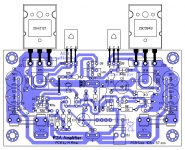
I already check this PCB layout with Rod Elliott original P3A Schematic, found This PCB layout is ok.But have some componant value changes, Can I use this PCB with Output as Tip 35/36 on +/-35VDC.Bellow, I attach All layers Pcb layout of Mr M.Mahai. please halp.
Hello All P3A builders
I found Rod Elliott P3A amp PCB on the following link https://elprojects.wordpress.com/2014/11/21/rod-elliott-amplifier-p3a/
I already check this PCB layout with Rod Elliott original P3A Schematic, found This PCB layout is ok.But have some componant value changes, Can I use this PCB with Output as Tip 35/36 on +/-35VDC.Bellow, I attach All layers Pcb layout of Mr M.Mahai. please halp.
Attachments
Last edited:
Hello All P3A builders
I found Rod Elliott P3A amp PCB on the following link https://elprojects.wordpress.com/2014/11/21/rod-elliott-amplifier-p3a/
I already check this PCB layout with Rod Elliott original P3A Schematic, found This PCB layout is ok.But have some componant value changes, Can I use this PCB with Output as Tip 35/36 on +/-35VDC.Bellow, I attach All layers Pcb layout of Mr M.Mahai. please halp.
Hy my friend ! You can use this pcb! I made 4 pcb`s exacly like this and it works, it`s ok.
Dear sanbadgujar,
Did your P3A worked with that PCB?
I made the same but, no music output.
I am getting response when I touch input capacitor.
Regards,
Sunita.
Did your P3A worked with that PCB?
I made the same but, no music output.
I am getting response when I touch input capacitor.
Regards,
Sunita.
If you guys look at the ESP original PCB, in the latest version pic - not the attempts posted here and elsewhere, you'll see that Q9 is clamped to one of the drivers. In fact, it should be at least very close or better, attached to either Q5 or Q6 for correct thermal compensation. P3 is a CFP type design and that is an important stability measure for the type, similar to mounting the Vbe multiplier transistor on the heatsink of common EF type designs.
Don't copy something that only manages to get the electrical circuit right. Get the compensation right too and it will be a more reliable, powerful amplifier rather than a liability that doesn't perform consistently.
Don't copy something that only manages to get the electrical circuit right. Get the compensation right too and it will be a more reliable, powerful amplifier rather than a liability that doesn't perform consistently.
- Home
- Amplifiers
- Solid State
- P3A PCB