So, i am doing P3A for college work, and i need to do calculations. I did DC calculations, now i started AC and already i have a problem.
This is a scheme ---> 60-80W Power Amplifier
Generator source voltage is 100 mV (70.7 mV RMS) with frequency 1 kHz
I am simulating project in Isis proteus so i`ll put some pictures so you can see where my problem is.
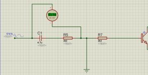
First picture is understandable, voltage across input filter is 70.7 mV and there is no problems.
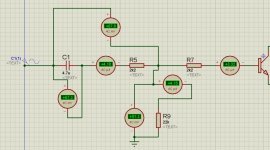
But, when i put only a resistor in parallel how it is in project scheme, i dont know what is happening anymore. (second picture)
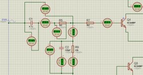
I am all confused when i put capacitor in parallel with resistor like in third picture.
I was trying with impedance calculations and many other things but never got same results like in simulator. So, if somebody of you guys understand this please give me an answer or just a path to follow 🙂
thank you very much
This is a scheme ---> 60-80W Power Amplifier
Generator source voltage is 100 mV (70.7 mV RMS) with frequency 1 kHz
I am simulating project in Isis proteus so i`ll put some pictures so you can see where my problem is.
First picture is understandable, voltage across input filter is 70.7 mV and there is no problems.
But, when i put only a resistor in parallel how it is in project scheme, i dont know what is happening anymore. (second picture)
I am all confused when i put capacitor in parallel with resistor like in third picture.
I was trying with impedance calculations and many other things but never got same results like in simulator. So, if somebody of you guys understand this please give me an answer or just a path to follow 🙂
thank you very much
Attachments
I may have missed something, but the sim results of your model look right.
Are you remembering that the capacitor has a 90degree phase shift?
A resistor in series with a capacitor gives a voltage across each component. But the "total" voltage across the pair does not "add" up to the individual voltages because the two voltages are 90 degrees to each other.
In diag2
Vcap=67.3mVac
Vtotal = 67.8Vac.
But if you add another voltmeter you will find that Vresistor is NOT 0.5mVac. It will be very much bigger than 0.5mVac.
Have you read about how to "add" out of phase voltages? Hint: A parallelogram should ring a bell.
Once you have understood what diagram2 can show you, you can extend that new knowledge to diagram3.
Last edited:
I may have missed something, but the sim results of your model look right.
Are you remembering that the capacitor has a 90degree phase shift?
A resistor in series with a capacitor gives a voltage across each component. But the "total" voltage across the pair does not "add" up to the individual voltages because the two voltages are 90 degrees to each other.
In diag2
Vcap=67.3mVac
Vtotal = 67.8Vac.
But if you add another voltmeter you will find that Vresistor is NOT 0.5mVac. It will be very much bigger than 0.5mVac.
Have you read about how to "add" out of phase voltages? Hint: A parallelogram should ring a bell.
Once you have understood what diagram2 can show you, you can extend that new knowledge to diagram3.
Yes of course, i understand the "parallelogram" calculation. Voltage of resistor which is in series with Cap is 9 mV. root of 67.3^2 + 9^2 = 67.8 mV
Thats ok, but i dont understand how to get voltage of resistor in parallel with input circuit (on picture 2), and when i put that resistor, i get voltage on Cap in input circuit. Why is that? and why is current in both circuits the same if they are parallel..
there is many questions 🙂 thank you for reply!
Which value confuses you?
Could it be the attenuator effect of the input network and the grounding network that follows it?
Ignore the capacitors for a moment.
Just use the resistors for the "passband" frequencies.
What is the attenuation effect of the resistors you have?
Does that help?
Could it be the attenuator effect of the input network and the grounding network that follows it?
Ignore the capacitors for a moment.
Just use the resistors for the "passband" frequencies.
What is the attenuation effect of the resistors you have?
Does that help?
- Status
- Not open for further replies.