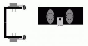
The other day I was thinking about how to make a Leach amp fit in a small case. I wanted to mount the output devices (4 times TO3 per chanel) on the PCB to minimize the amount of wires. This would make the boards become quite large. Therefor I thought it should be split into an output board and a small signal board, similar to what Jens shows us in <a href="http://www.diyaudio.com/forums/showthread.php?threadid=4091">this thread</a>.
Then suddenly I found myself thinking about point to point wiring the output part. This would include everything from Q14/15 and out. The more I thought about it, the more logical it seemed. Just make an arrangement like on the image below, where Q16 through Q21 mount on angular alu profiles on the heat sinks. The rest is point to point wired to these transistors.
The small signal board could then be made quite small, and maybe even fastened to the aluminium profiles.
What do you think about this idea? There will have to be wires for the feedback loop - just how bad is this?
-truls
