"Perhaps someone else would like to try to explain to you that transformer iron does not lose all its permeability at zero flux."
Here are pages 61 through 63 of "Magnetism and Metallurgy of Soft Magnetic Materials" by Chih-Wen Chen
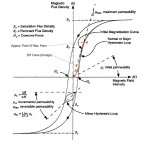
ESL... may be confusing the lower initial permeability region I (instantaneous slope of B versus H on the curve) as a drop off to zero permeability. It is still quite finite and useable. The higher permeability region II in the graph of Fig. 3.1 is caused by avalanching of magnetic domains under high impedance current drive. (adjacent domains can trigger a domino like effect) With a low Z output stage, this is controlled, so that only sufficient flux change as mandated by the winding voltage is allowed.
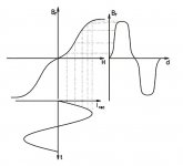
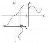
Figure 3.2 shows that under steady large signal excitation, the initial permeability region is replaced by the highest permeability from avalanching across the zero flux region. So zero crossing is actually the easiest region for large signals (least magnetizing current region in P-P AC flux mode). And the minor loop shown in Fig. 3.2 shows what happens for a small signal (similar in either the P-P zero bias case, or the DC biased SE case), the permeability reverts to the initial permeability slope. However, SE is ALWAYS operating in the lower initial permeability (minor loop) region because of the pinned down domains from the DC bias prevent avalanching. So one can only say that SE mode operates 100% of the time in the worst case P-P initial perm. region. But the mostly higher permeability regions in the P-P case mean less magnetizing current imposed on the output tubes.
For the SE case, larger signals mean the expansion of the minor loop to cover the full voltage (flux) swing. The ellipse area gets bigger as the square of the flux (voltage) change. By the time you get that minor loop to cover a large swing, like equivalent to the full hysteresis curve height, the ellipse will enclose MORE area than the usual S curve. (Hysteresis is proportional to the area enclosed by the curves.) And the low permeability will mean high magnetizing current to do that. This is like controlled flight into ground.....
Here are pages 61 through 63 of "Magnetism and Metallurgy of Soft Magnetic Materials" by Chih-Wen Chen
ESL... may be confusing the lower initial permeability region I (instantaneous slope of B versus H on the curve) as a drop off to zero permeability. It is still quite finite and useable. The higher permeability region II in the graph of Fig. 3.1 is caused by avalanching of magnetic domains under high impedance current drive. (adjacent domains can trigger a domino like effect) With a low Z output stage, this is controlled, so that only sufficient flux change as mandated by the winding voltage is allowed.
Figure 3.2 shows that under steady large signal excitation, the initial permeability region is replaced by the highest permeability from avalanching across the zero flux region. So zero crossing is actually the easiest region for large signals (least magnetizing current region in P-P AC flux mode). And the minor loop shown in Fig. 3.2 shows what happens for a small signal (similar in either the P-P zero bias case, or the DC biased SE case), the permeability reverts to the initial permeability slope. However, SE is ALWAYS operating in the lower initial permeability (minor loop) region because of the pinned down domains from the DC bias prevent avalanching. So one can only say that SE mode operates 100% of the time in the worst case P-P initial perm. region. But the mostly higher permeability regions in the P-P case mean less magnetizing current imposed on the output tubes.
For the SE case, larger signals mean the expansion of the minor loop to cover the full voltage (flux) swing. The ellipse area gets bigger as the square of the flux (voltage) change. By the time you get that minor loop to cover a large swing, like equivalent to the full hysteresis curve height, the ellipse will enclose MORE area than the usual S curve. (Hysteresis is proportional to the area enclosed by the curves.) And the low permeability will mean high magnetizing current to do that. This is like controlled flight into ground.....
Attachments
Last edited:
Boy, I'm really late to the tea party, but I have a few decade-long ideas that I wonder if y'all could write a quick response to.
The flyback effect AKA stored energy
In a PP amplifier, whether the valves are operation in A, AB or even B bias points, the nominal notion is that the in-phase and anti-phase (inverted) biases through the output transformer are balanced. Why? because that is the design, and because that 'zeroes out' or cancels the net flux in the core, giving largest headroom to subsequent amplified-signal voltage/current swings.
In an SE amplifier “more or less” the quiescent current is set to about 50% of what the saturation current is specified as, for the core of the transformer and all its primary-side windings. Again, kind of makes sense: the core can have excursions significantly close to saturation, and down almost to zero … and remain largely in its linear magnetic transconductance region. Cool! As DC doesn't 'couple' across from primary to secondary, the output at the speaker terminals is nominally 'zero', but becomes nice A/C tracking the input as one would expect.
That is not a question.
The question is, might the stored energy within the SE output transformer be materially affecting the response of the output tube because of the out-of-phase buck voltage or 'flyback voltage' induced as current changes? I mean, there IS an inductor there, and its stored energy has to go somewhere that fits onto the normative V(t) = L di/dt equation. Dunno … maybe I'm just confused since as a coupled inductive device, the V(t) = L di/dt equation is far too simple, and the quenched quiescent current (energy) of the transformer is just transferred to the output terminals, and then 'sucked up' by the speaker-driver motors when turning the power into sound pressure.
But If there's a bit of truth in considering the fact that a SE transformer nominally has a lot of magnetic stored energy at quiescence, and it is going to have to shed that power as the valve 'valves' with the signal, whereas the push-pull by definition will not have that stored energy at quiescence … methinks that this fact alone will change how the interplay between magnetic devices (speaker and output transformer) cause material differences in the production of acoustic sound pressure, instant-by-instant.
And if that's even modestly right - then there should be an acoustic difference in the reproduction of the input signal between topologies. Not just from harmonics.
I guess the answer might just as simple as hooking up a pair of nominal speakers to each kind of amplifier, then using a current-sense low-value series resistor, measure both dV/dt and dI/dt for the 2 topologies of nominally similar amplifiers.
But it remains a question to me.
SECOND (whew!) a real simple idea/question: Could one effectively emulate the zero-crossing regime of a push-pull amplifier with a SE setup by using a PP transformer, and taking the 'other half' of the primary and running a servo-balanced amount of CURRENT thru it to counter the magnetic flux of the “first half”? Seems like an almost trivial thing to do, as it would be pretty easy to use a high impedance tap of the “first half's” SE output tube and run it into a low LPF to calculate an average voltage .. which then could be “drained out” by a heat-sinked high-voltage transistor as the current sink. The transformer would then have “auto-balanced” current flow in opposite directions, thus canceling magnetic flux. The SE would then have the advantages of a PP 'zero-flux crossing' magnetic non-storing domain.
Dunno… I've not heard of it - but then again, I've not heard of many things.
GoatGuy
Considering a simple case of sine wave excitation from the driving tubes. The primary voltage determines the flux change in the core, and that in turn determines the voltage (with turns ratio) at the secondary. The core inductance determines a magnetizing current from any imposed voltage. For a sine wave, this current is a 90 degrees out of phase (lagging) sine wave from the imposed voltage, so power flows into and back out of the inductance (ie, the B field) during each quarter of the wave (depending on product of signs of V and I).
Normally we think of the driving tube as handling this magnetizing current flow, because it is a voltage source and will permit no deviation from its commands. But if the input were suddenly dis-connnected, this inductive power would then be released into the load like a flyback. So, in a sense, the magnetic induction current can be seen as assisting the driver tube, if it agrees in polarity, (so the induction current IS driving the load in that situation by not requiring that current from the tube to null it out), but it is just as likely (50% of the time with a random audio signal) to be in the wrong direction (so doubling the tube's headache at those times). So basically, net result, the magnetizing current could just as well be coming from a separate inductor in parallel with the (ideal) xfmr primary.
------------------------------
For using a P-P OT for SE, one should ideally only need a CCS across the other primary half to equalize out opposing DC currents. The current source wants to be a high impedance so as to not short out the AC signal on the OT. For a SE like driver though, 2nd harmonic distortion from the tube at large amplitudes will unbalance this somewhat, so a slowly tracking servo could have some benefit if the OT cannot handle some imbalance. (an E I core would have the best chance, maybe stack all the E's and I's the same way to make for a tiny effective gap, it only has to handle the 2nd Harmonic imbalance.)
The SE OT likely has another 2nd harmonic effect from the signal swinging the core from zero to max flux. There will be a variation in core permeability as more to less magnetic domains are available to support the flux change. (just like the perm drops for a P-P case at +/- Bmax, but here for SE it would be unidirectional) AC transformers develop 3rd harmonic distortion currents from permeability change, while the SE xfmr will generate 2nd harmonic current distortion. That's 90 degrees out of phase with the tube's 2nd harmonic distortion, so no cancelling is possible here.
Last edited:
One interesting application comes from the idea of using the stored energy in a gapped OT. Consider a gapped ferrite core, operating as a switched mode HF converter from low voltage DC to high voltage DC. The primary side has a HF SS switch from LV DC to "charge up" the magnetic flux periodically as the secondary load draws the current back off. (flyback mode regulator or Boost/ Buck converter)
Now consider the same setup with TWO secondary windings. One LV secondary, and one HV secondary. The primary HF switching circuit still keeps the core flux "charged up". Now we can draw the current off from either the LV secondary at higher current, or from the HV secondary at lower current. OR BOTH as a turns ratio'd sum. (multi voltage output switch mode converters typically operate just this way)
So now we put a speaker load across the LV secondary, and a tube across the HV secondary. (then using two of these full setups, with reversed LV secondary polarity across the speaker, like a Circlotron, to get bi-directional current into the speaker)
Now if the primary switching circuit keeps dumping steady current into the core flux, then the sum of the LV and HV secondary currents (turns ratio apportioned) must draw off the equivalent current sum to keep the core at steady magnetic field. So by controlling the tube current draw from the HV secondary, we can control the current available from the LV secondary in complementary fashion. Modulating the tube effectively drives the speaker load current in complementary fashion. And using two complementary polarity setups (Circlotron, or even totem pole fashion) allows bidirectional AC current drive to the speaker by phase complementary modulation of the two tubes. Sounds like P-P.
So we get a HV supply AND an impedance matching OT all in one little ferrite xfmr (well two ferrite xfmrs for the full P-P, bi-directional current, setup as above). Since the primary sides operate from LV, they can be supplied by a LV commercial switch mode supply, with the UL/EIA power line isolation built in. So we can use a very simple minded ferrite converter(s) setup for our OT, probably just an IC driver chip for each ferrite core.
This is NOT the same as the Berning switched mode ferrite OT, which uses voltage mode conversion instead. This new current mode HF OT setup would require a feedback loop for the tubes to lower the output Z to the speaker, since each ferrite LV secondary output looks pentode like (but high current capable).
One can also produce this as an SE arrangement. One ferrite/tube converter acting as the SE audio control element (but high current out), and use a switched mode inductor alone for the other polarity element. (this is just a dual LV primary winding HF ferrite version with alternating DC into the two phase reversed windings, to act like a switch mode DC current source at the other winding ends. Ie, the dual windings act like a DC reactance externally, but AC reactance internally.)
Last edited:
Yes, there is stored energy in an SE OPT due to the DC current but, to a first approximation, it does not vary during the AC cycle. This is because transformer action ensures that the change in flux due to current in the primary is almost exactly balanced by the change in flux due to current induced in the secondary.GoatGuy said:But If there's a bit of truth in considering the fact that a SE transformer nominally has a lot of magnetic stored energy at quiescence, and it is going to have to shed that power as the valve 'valves' with the signal, whereas the push-pull by definition will not have that stored energy at quiescence … methinks that this fact alone will change how the interplay between magnetic devices (speaker and output transformer) cause material differences in the production of acoustic sound pressure, instant-by-instant.
Yes, but much better to drive the other side too and get P-P. Why waste even more power than SE already wastes?SECOND (whew!) a real simple idea/question: Could one effectively emulate the zero-crossing regime of a push-pull amplifier with a SE setup by using a PP transformer, and taking the 'other half' of the primary and running a servo-balanced amount of CURRENT thru it to counter the magnetic flux of the “first half”?
Thanks for that. It shows precisely what I have been trying to tell you: that permeability does not disappear at the origin! The curve is not horizontal.
You not see the lower levels where it is practical horizontal....
Thanks for that. It shows precisely what I have been trying to tell you: that permeability does not disappear at the origin! The curve is not horizontal.
Attachments

Last edited:
Your graph in post 46 clearly shows initial permeability is non-zero, and similar in magnitude (although a bit smaller) than the permeability elsewhere.
Your graph in post 48 similarly shows quite clearly that nowhere (apart from saturation) does the graph approach horizontal.
Thanks for providing evidence for what I have been saying.
Your graph in post 48 similarly shows quite clearly that nowhere (apart from saturation) does the graph approach horizontal.
Thanks for providing evidence for what I have been saying.
It just drops down to Mu sub i, or initial permeability. That's one of the specs for magnetic materials. Its never zero. And that's what you get anyway using SE, with all the easy magnetic domains pinned down by the DC bias field. The higher permeability regions with larger signal are from avalanching domains, available with AC only. The SE DC bias field is so strong, that only half the magnetic domains are left functioning, and those are the high anisotropy ones (high friction). It's like throwing dirt into your car engine intake to prevent high revving noises.
Last edited:
These graphs are very rough, just showing larger exitating levels. I am more interested in a picture where i can see a level lower then 0,0002 Tesla.
If you have some i would apreciated that.
If you have some i would apreciated that.
Your graph in post 46 clearly shows initial permeability is non-zero, and similar in magnitude (although a bit smaller) than the permeability elsewhere.
Your graph in post 48 similarly shows quite clearly that nowhere (apart from saturation) does the graph approach horizontal.
Thanks for providing evidence for what I have been saying.
Having provided evidence that he is mistaken, esltransformer now casts doubt on his own evidence! I guess there is no convincing some people when they get a wrong idea in their head.
I alway mented at low levels, at medium to high levels there is nothing interesting about permeability.
At still my -3dB point changes.....
At still my -3dB point changes.....
Having provided evidence that he is mistaken, esltransformer now casts doubt on his own evidence! I guess there is no convincing some people when they get a wrong idea in their head.
Last edited:
Faraday's law guarantees that voltage detail will go through the OT as long as the leakage L is not huge. Guess which OT: P-P or SE has more leakage L?
Permeability only affects the magnitude of the magnetizing current. Low Rp outputs (or local N Fdbk) will overcome the magnetizing current. Almost anything will work at just 0.0002 Tesla. But the initial permeability is steady anyway.
Lack of detail is not the fault of the OT anyway. Class aB or B looses detail due to low gm in the output stage at low currents around crossover. Class A overcomes that by running at high current (the effective sum for P-P).
( N Fdbk will of course fix class AB).
However, I suspect that when someone says they hear subtle detail, they really mean there is no annoying HF bandwidth to clutter up the low level listening. SE is pretty good at that.
Last edited:
I did mean a referance at my post 21, a pp transformer
Did you too mean post 21?
Did you too mean post 21?
Faraday's law guarantees that voltage detail will go through the OT as long as the leakage L is not huge. Guess which OT: P-P or SE has more leakage L?
Permeability only affects the magnitude of the magnetizing current. Low Rp outputs (or local N Fdbk) will overcome the magnetizing current. Almost anything will work at just 0.0002 Tesla. But the initial permeability is steady anyway.
Lack of detail is not the fault of the OT anyway. Class aB or B looses detail due to low gm in the output stage at low currents around crossover. Class A overcomes that by running at high current (the effective sum for P-P).
( N Fdbk will of course fix class AB).
However, I suspect that when someone says they hear subtle detail, they really mean there is no annoying HF bandwidth to clutter up the low level listening. SE is pretty good at that.
Very great input from the 'theory of domains' smoking-amp.
Great ideas from goatguy: I don't understand your simulation of SET with PP transformer... thinking of running the output with a choke and capacitor coupling the PP transformer won't reach your experiment goals for a reason that I ignore.
I think the cut in the core prevent that DC to magnetize the core in SET, so I disagree that SET transformers are already 50% saturated domains at no signal. However, you are right for the current required to excite the core will be proportionally greater than in a PP, which is compensated with the added size to sustain the higher currents. The major benefit of the SET is that the AC signal keeps the magnetic field in the same orientation which sustains a better linearity of the magnetic core.
Last edited:
You mean something like this? (see pictures)
Very great input from the 'theory of domains' smoking-amp.
Great ideas from goatguy: I don't understand your simulation of SET with PP transformer... thinking of running the output with a choke and capacitor coupling the PP transformer won't reach your experiment goals for a reason that I ignore.
I think the cut in the core prevent that DC to magnetize the core in SET, so I disagree that SET transformers are already 50% saturated domains at no signal. However, you are right for the current required to excite the core will be proportionally greater than in a PP, which is compensated with the added size to sustain the higher currents. The major benefit of the SET is that the AC signal keeps the magnetic field in the same orientation which sustains a better linearity of the magnetic core.
Attachments
Yes Elstransformers, if the designer of the amp knows how to bias the transformer it is exactly that linear section of the Cartesian graph. (as a pessimist I think most SET designs miss that optimal point, under-bias / over-bias)
You cannot just move over to the linear portion of the graph by biasing. Wherever you operate, the remaining (operational) magnetic domains re-establish an hysteresis curve around that new point.
An AC signal requires magnetic domains to be flipping to satisfy Faraday's law (flux change rate proportional to voltage). As you increase the DC bias, more domains are disabled, the hysteresis curve produced by the remaining useable domains gets thinner and more ellipse like. A lower initial permeability range exists around the new operating point, just like before. Fewer domains are available for avalanching, so the high perm. region shrinks (the linear part on the curve), eventually (with enough DC) becoming just an ellipse with low (= initial) permeability (at least up to near saturation region).
For the magnetization curve just shown, this means it shifts over with the DC bias. So operation still occurs around the curvy (central) part. Use more DC and the curve progressively looses the high slope (linear) regions, eventually becoming just the low slope (central) region everywhere.
There is also a fundamental error in the association of input to output as a gain function in that graph. Faraday's law sets the gain via the flux change rate per volt turn. Permeability has nothing to do with the gain function. That just determines the magnetizing current level. A very flawed graph illustration. (The actual graph is probably showing magnetizing current input to flux level for zero DC bias. But the implication via waveforms that that is setting a voltage gain is just plain wrong.)
Last edited:
You are right that there is still hysteresis but as with many pictures they just show part of the "truth". In this case -permalloy- the hysteresis is so small you can not see it in the picture.
The picture has no values at X&Y ax so gain?
The picture has no values at X&Y ax so gain?
You cannot just move over to the linear portion of the graph by biasing. Wherever you operate, the remaining (operational) magnetic domains re-establish an hysteresis curve around that new point.
An AC signal requires magnetic domains to be flipping to satisfy Faraday's law (flux change rate proportional to voltage). As you increase the DC bias, more domains are disabled, the hysteresis curve produced by the remaining useable domains gets thinner and more ellipse like. A lower initial permeability range exists around the new operating point, just like before. Fewer domains are available for avalanching, so the high perm. region shrinks (the linear part on the curve), eventually (with enough DC) becoming just an ellipse with low (= initial) permeability (at least up to near saturation region).
For the magnetization curve just shown, this means it shifts over with the DC bias. So operation still occurs around the curvy (central) part. Use more DC and the curve progressively looses the high slope (linear) regions, eventually becoming just the low slope (central) region everywhere.
There is also a fundamental error in the association of input to output as a gain function in that graph. Faraday's law sets the gain via the flux change rate per volt turn. Permeability has nothing to do with the gain function. That just determines the magnetizing current level. A very flawed graph illustration. (The actual graph is probably showing magnetizing current input to flux level for zero DC bias. But the implication via waveforms that that is setting a voltage gain is just plain wrong.)
- Status
- Not open for further replies.
- Home
- Amplifiers
- Tubes / Valves
- P-SET EL34