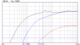
Here a measurement i made at different levels (i used also a 1:10 probe so actual there are 3 different levels). From about 6Hz to 40Hz at lower level (and not even measured at very low level)
This transformer is from a well know audio company, material M4 EI laminations.
This transformer is from a well know audio company, material M4 EI laminations.
Attachments
Last edited:
You appear to be confusing two different things. The permeability may reduce at low flux levels, and hence give rise to a reduction in inductance, but it certainly does not disappear - as your results show. So no "horizontal slope", just a more gentle slope.esltransformer said:If it is a slope as you say then at a certain point the slope is horizontal.
Btw, The induction drops rapidly at low levels.
In reality it is usually found that valve amplifiers have wider bandwidth at lower levels. Or are you suggesting that at very low levels the bandwidth narrows again?
This graph measurement looks like a typical Xfmr frequency response curve. The low frequency drops off, as expected, due to low reactance at low frequency (f).
Xl = 2 pi f L
Nothing to do with the core material permeability.
SE cores actually perform far worse than P-P cores due to the DC field saturating the easy to flip (high permeability) magnetic domains. They are stuck in one direction and useless. The core is left with the hard to flip domains to work with for AC. The addition of the air core to prevent the loss of all domains completely then lowers the inductance of the core so one suffers exactly the lack of L as you have shown above. SE OTs absolutely SUCK in every respect.
The idea of no "crossover" effects in a SE OT results from a misreading of the usual hysteresis curve.
The higher inductive current, from the consequent lower inductance, hides the small hysteresis effect better. But the hysteresis is still there from the remaining hard to flip domains handling the AC. And it is HIGHER per signal level with harder to flip domains, just better hidden with the huge magnetizing current from the low inductance (from the air gap). SE proponents have long advertised the lower hysteresis without knowing that it is actually higher for SE. The old story about if you repeat a lie enough times..... It has become one of the many standard audio lies for advertising purposes.
The presence of ANY transferred AC signal across a core winding requires the flipping of a proportionate amount of magnetic flux. (Faraday's law) There is no escaping flipping of magnetic domains for either SE or P-P modes. P-P, at least, uses the easiest to flip (and the most numerous still available) magnetic domains.
Last edited:
i think you are confused yourself. There is no magneticfield at some levels.
I your case we can use SiFe even for microphone or mc cartridges because you say there will be always permeability and a magneticfield.
I your case we can use SiFe even for microphone or mc cartridges because you say there will be always permeability and a magneticfield.
You appear to be confusing two different things. The permeability may reduce at low flux levels, and hence give rise to a reduction in inductance, but it certainly does not disappear - as your results show. So no "horizontal slope", just a more gentle slope.
In reality it is usually found that valve amplifiers have wider bandwidth at lower levels. Or are you suggesting that at very low levels the bandwidth narrows again?
You not explaning anything. Please explane why there is less reactance.
You are right that in se there is also a hysteresis but the differance is that there is always a magnetic field. Because of the airgap the permeability loop is almost flat (actual an Oval), not lower. And also in se you can see that low frequancy response is less good at lower levels.
You are right that in se there is also a hysteresis but the differance is that there is always a magnetic field. Because of the airgap the permeability loop is almost flat (actual an Oval), not lower. And also in se you can see that low frequancy response is less good at lower levels.
This graph measurement looks like a typical Xfmr frequency response curve. The low frequency drops off, as expected, due to low reactance at low frequency (f).
Xl = 2 pi f L
Nothing to do with the core material permeability.
SE cores actually perform far worse that P-P cores due to the DC field saturating the easy to flip (high permeability) magnetic domains. They are stuck in one direction and useless. The core is left with the hard to flip domains to work with for AC. The addition of the air core to prevent the loss of all domains completely then lowers the inductance of the core so one suffers exactly the lack of L as you have shown above. SE OTs absolutely SUCK in every respect.
The idea of no "crossover" effects in a SE OT results from a misreading of the usual hysteresis curve.
The higher inductive current with the lower inductance hides the small hysteresis effect better. But the hysteresis is still there from the remaining hard to flip domains handling the AC. And it is HIGHER per signal level with harder to flip domains, just better hidden with the huge magnetizing current from the low inductance (from the air gap). SE proponents have long advertised the lower hysteresis without knowing that it is actually higher for SE. The old story about if you repeat a lie enough times..... It has become one of the many standard audio lies for advertising purposes.
The presence of ANY transferred AC signal across a core winding requires the flipping of a proportionate amount of magnetic flux. (Faraday's law) There is no escaping flipping of magnetic domains for either SE or P-P modes. P-P, at least, uses the easiest to flip (and the most numerous still available) magnetic domains.
Last edited:
"Please explane why there is less reactance."
Umm, ANY textbook on magnetics or introductory physics (Faraday's law) will explain this:
Xl = 2 pi f L
Try "MIT Magnetic Circuits and Transformers"
or "Transformers for Electronic Circuits" by Nathan Grossner
or "Practical Transformer Design Handbook" by Eric Lowden
or "Handbook of Transformer Design & Applications" by Flanagan
or "Electronic Transformers and Circuits" by Reuben Lee
or even "Radio Designer's Handbook" Langford-Smith
Last edited:
Way to easy..... Please come with an answer.
"Please explane why there is less reactance."
Umm, ANY textbook on magnetics will explain this.
Try "MIT Magnetic Circuits and Transformers"
or "Transformers for Electronic Circuits" by Nathan Grossner
or "Practical Transformer Design Handbook" by Eric Lowden
or "Handbook of Transformer Design & Applications" by Flanagan
You seem to be mixing up zero field and zero slope. As I said, does resistance disappear when no voltage is applied? I said there is always permeability; I did not say that there is always a magnetic field. Why not deal with what I say, and not what I don't say?esltransformer said:i think you are confused yourself. There is no magneticfield at some levels.
I your case we can use SiFe even for microphone or mc cartridges because you say there will be always permeability and a magneticfield.
Permeability is a slope, not a ratio, therefore it is well-defined at zero field.
So you say its all about a definition.
Dosn't help to solve the transformer problem.
Btw dos a resistor have hysteresis?
Sorry you did not say that but if there would be always permeability there would be also always a magnetic field if there would be any signal. But this is not the case! It's more a diode then a resistor maybe.
Dosn't help to solve the transformer problem.
Btw dos a resistor have hysteresis?
Sorry you did not say that but if there would be always permeability there would be also always a magnetic field if there would be any signal. But this is not the case! It's more a diode then a resistor maybe.
You seem to be mixing up zero field and zero slope. As I said, does resistance disappear when no voltage is applied? I said there is always permeability; I did not say that there is always a magnetic field. Why not deal with what I say, and not what I don't say?
Permeability is a slope, not a ratio, therefore it is well-defined at zero field.
Last edited:
https://en.wikipedia.org/wiki/Electromagnetic_induction
https://en.wikipedia.org/wiki/Electrical_reactance#Inductive_reactance
---------------------------
The reason the permeability loop looks almost flat for the gapped core case is because they are comparing with the un-gapped case with the same CURRENT swing typically. But the low effective permeability of the gapped SE case requires more like 10X the current swing of the non-gapped P-P case to support the same VOLTAGE swing. Voltage swing is the limitation for an Xfmr. (copper winding resistance determines the current swing limitation) The hysteresis loss typically grows at a rate greater than the SQUARE of the voltage swing, so the real SE hysteresis is actually bigger than P-P.
----------------------------
Which applies to the earlier question of using a large P-P OT at low signal levels. The losses (including hysteresis) will typically be lower for the bigger OT with lower signal. One has to work out the core volume ratios and the square of the signal levels to determine the outcome.
This impacts on the typical SE OT results too, since they have to use 3 to 4X bigger cores to support the same Watts throughput. They SHOULD have lower hysteresis just from that, if it were not for the core gap effects making things worse.
Last edited:
Nice, thank you, but not an answer on my question.
Secondly your answer on why the airgapped transformer has a flat hystersis loop is not so good.
You can read that in the articles of Partridge but at this point i am not so interessted in this.
Secondly your answer on why the airgapped transformer has a flat hystersis loop is not so good.
You can read that in the articles of Partridge but at this point i am not so interessted in this.
https://en.wikipedia.org/wiki/Electromagnetic_induction
https://en.wikipedia.org/wiki/Electrical_reactance#Inductive_reactance
---------------------------
The reason the permeability loop looks almost flat for the gapped core case is because they are comparing with the un-gapped case with the same CURRENT swing typically. But the low effective permeability of the gapped SE case requires more like 10X the current swing of the non-gapped P-P case to support the same VOLTAGE swing. Voltage swing is the limitation for an Xfmr. (copper winding resistance determines the current swing limitation)
Last edited:
No. Once again you attribute to me something I did not say.esltransformer said:So you say its all about a definition.
The issue is not definitions, but understanding. You appear not to understand the distinction between a ratio (which becomes undefined when one of the factors is zero) and a slope (or differential, which can be perfectly well defined at the origin).
Hysteresis is not the issue. The fact that you appear to think it is concerns me. The issue is nonlinearity. You still seem to be connecting non-zero permeability with non-zero magnetic field; two completely different issues.Btw dos a resistor have hysteresis?
Sorry you did not say that but if there would be always permeability there would be also always a magnetic field if there would be any signal. But this is not the case! It's more a diode then a resistor maybe.
"Nice, thank you, but not an answer on my question."
One can lead a horse to the water, but one cannot make the horse drink it.....
The higher magnetizing current required for the SE case (aside from any hysteresis), versus the P-P case, also makes for increased output tube distortion generation (aside from the OT internal core effects). But the SE user is happily paying for that at least.
In any case (SE or P-P), just by using a low output impedance tube stage (local N Fdbk) will essentially remove any Xfmr hysteresis effects. One can obviate the need for gold/silver/amorphous/whatever with just a resistor or two.
Obviously the OT advertisers will not inform you of this inconvenience (to them).
Last edited:
For pp (and much less se) linearity is certainly an isue, i did not say it wasn't. But hysteresis is certainly also an issue.
It concerns me also that you compare it with a restistor.
It concerns me also that you compare it with a restistor.
No. Once again you attribute to me something I did not say.
The issue is not definitions, but understanding. You appear not to understand the distinction between a ratio (which becomes undefined when one of the factors is zero) and a slope (or differential, which can be perfectly well defined at the origin).
Hysteresis is not the issue. The fact that you appear to think it is concerns me. The issue is nonlinearity. You still seem to be connecting non-zero permeability with non-zero magnetic field; two completely different issues.
Linearity for SE is much worse than P-P due to the higher magnetising current effects on the tubes.
(which has nothing much to do with the slight hysteresis distortion)
One needs to concern oneself with the broken leg before worrying about the fleas.
(which has nothing much to do with the slight hysteresis distortion)
One needs to concern oneself with the broken leg before worrying about the fleas.
It is a useful analogy to illustrate what I perceived to be your fundamental misunderstanding. Just as zero voltage does not imply zero resistance in a conductor, so zero field does not imply zero permeability in a ferromagnet.esltransformer said:It concerns me also that you compare it with a restistor.
The only think is that your analogy is completely wrong, it has nothing to do with a resistor. It has hysteresis and no resistor has hysteresis.
If it was an aircore you have a point but it is neither an aircore.
If it was an aircore you have a point but it is neither an aircore.
It is a useful analogy to illustrate what I perceived to be your fundamental misunderstanding. Just as zero voltage does not imply zero resistance in a conductor, so zero field does not imply zero permeability in a ferromagnet.
And why is higher magnetisation current simular to lower linearity?
Linearity for SE is much worse than P-P due to the higher magnetising current effects on the tubes.
(which has nothing much to do with the slight hysteresis distortion)
One needs to concern oneself with the broken leg before worrying about the fleas.
The OT magnetizing current is out of phase (90 degrees) with the actual signal. And it is frequency dependant too, worse at low frequency. Since the tubes have a finite output impedance, this unwanted current directly distorts (modifies) the intended output signal. The load line on the tube plate curves becomes an ellipse, rather than a straight (and narrow) load line as designed. Putting the tube operating point closer to the curved knee portions of the plate curves during half the signal cycle. This causes a form of "tube hysteresis" effect, much bigger than the OT hysteresis. (There is also a real internal tube hysteresis effect, as N. Crowhurst described once. But that is not related to this.)
Lowering the output impedance of the tube stage via some local N Fdbk is a competent fix for the magnetizing current. Or just using some low Rp tubes. It also, incidently, handles the much smaller OT hysteresis current besides. And it improves the bandwidth of the OT and speaker damping factor (better bass). This is a 1st magnitude improvement.
Putting in silver/gold/amorphous/nano-crystalline ... are very 2nd order improvements. Of course, P-P starts with miniscule magnetizing current (except at the low freq. bandwidth limit) to begin with, compared to SE Op. already.
When one sees endless super expensive fixes applied to SE, without fixing the 1st order problem, the image of a gold plated t_rd comes to mind easily.
Last edited:
OK. You clearly don't grasp the point I have been repeatedly making. I hoped a simple analogy would help you, but instead you are quibbling about an irrelevant side issue. Maybe at this point I should give up and leave you with your misunderstanding.esltransformer said:The only think is that your analogy is completely wrong, it has nothing to do with a resistor. It has hysteresis and no resistor has hysteresis.
Perhaps someone else would like to try to explain to you that transformer iron does not lose all its permeability at zero flux.
- Status
- Not open for further replies.
- Home
- Amplifiers
- Tubes / Valves
- P-SET EL34