this circuit seems ok until the output reaches around 14v peak to peak, then i get an overshoot on the rising edge top only.
below 14vpp, the 47p miller gives a nice square with slightly rolled off corners, input signal is 10khz square.
any ideas? the ltpsice sims do not show this behaviour.
below 14vpp, the 47p miller gives a nice square with slightly rolled off corners, input signal is 10khz square.
any ideas? the ltpsice sims do not show this behaviour.
Attachments
I would guess Early effect or Ccb nonlinearity in Q8, Q7, or an appreciably nonlinear C10.
See whether a C-B capacitor on Q8 has any effect, and try another C10 (or if you have a bunch of 'em, 4 in 2S/2P).
See whether a C-B capacitor on Q8 has any effect, and try another C10 (or if you have a bunch of 'em, 4 in 2S/2P).
Hi
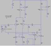
The circuit can't work as drawn.
V1 is upside down, although because you've labelled it as "-40" the ends are actually opposite to the supply symbol marking?
The circuit is not likely able to drive the 15k feedback resistor. Add an EF and connect Rfb to it and it should swing practically rail to rail.
You should also add a large cap between R5 and ground so DC gain will be one.
How is your high frequency bypassing on the board?
You're also saturating the input stage because it's running out of current to push the 47 pF miller cap.
Would it be ok to put a pole at the input to de-fang the square wave a bit?
You're also saturating the input stage because it's running out of current to push the 47 pF miller cap.
Would it be ok to put a pole at the input to de-fang the square wave a bit?
i have tried various miller caps with the same result.
nauta, did you miss Q12?
bypassing is 100u/100n for each rail.
how much current is enough for the miller cap?
i will be using 390p to filter the input, but for these tests it was omitted.
i will added some scope shots shortly.
nauta, did you miss Q12?
bypassing is 100u/100n for each rail.
how much current is enough for the miller cap?
i will be using 390p to filter the input, but for these tests it was omitted.
i will added some scope shots shortly.
miller cap current depends how fast you want output to slew...10V/us time 47 pF says you need to charge or discharge the cap with 0.47 mA...let's call it half a milliamp...
Do you want 20 v/us? you need 1 mA to charge or discharge the cap.
100 v/us? 5 mA!
Your current source is 0.6/330=1.8 mA. All of it can pull up or pull down, but after that, the loop is kind of out of control and has to recover...that absolute limit on slew rate...upper bound, would be 1.8e-3/47e-12*1e-6=38 v/us.
With your plus and minus 40 volt rails, it would take a bit more than 2 microseconds to slew from the negative rail to the positive rail.
Hitting slew rate limits sounds very probable, actually. On an amplifier like this, slew rate tends to be unbalanced.
They say you can have either the small-signal bandwidth or the slew rate, but not both at the same time! This dirty little secret isn't too widely known.
This comes about since as one half of the input pair is scrambling for current to charge the Miller cap, the other half gets starved for current and becomes correspondingly s-l-o-w-e-r. Simulation may have overestimated remaining GBW in this case, so real-life input transistor Cob may be substantially larger than assumed. Try some different types, try a cascode. One reason why complementary differential input topologies enjoy a certain popularity.
If achieved slew rate is well within the green, use some input RC filtering to (literally) take the edge off. There is no reason for the bandwidth of an audio amplifier to extend beyond 50-100 kHz.

How is the real circuit built? This kind of effect can often occur with bread boarded circuits due to coupling between parallel strips of the plug board.
R13 is bias for next stage, shorting it made no change.
the cct is built on a proper pcb, albeit with a couple of mods, however i will look at it again.
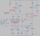
i will try out mod 2, for mod 1 i have tried this additional compenstation with 5p/10p but not sure why you have shown an extra "R13"
the cct is built on a proper pcb, albeit with a couple of mods, however i will look at it again.
i will try out mod 2, for mod 1 i have tried this additional compenstation with 5p/10p but not sure why you have shown an extra "R13"
Since the overshoot is clean, without after-ringing, I would agree with Grossklass: the SR exceeds the limits of the circuit, and it needs some time to recover afterwards.
As a diagnostic help (not necessarily a final fix), I would try an antisaturation diode on Q5; a small schottky would do: some kind of BATxy
As a diagnostic help (not necessarily a final fix), I would try an antisaturation diode on Q5; a small schottky would do: some kind of BATxy
it seems the scope probe was upsetting the circuit (measurement point Q8c)
i set the probe to X10 and now i have a good clean square.
i set the probe to X10 and now i have a good clean square.
- Home
- Amplifiers
- Solid State
- overshoot when output is raised