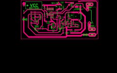
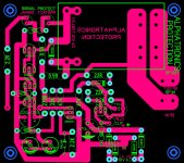
Hello Guys. I upload this schematic that contains several protect circuits such as DC, overload and clip detect. But the only thing I ask you is about the overload circuit, specially how to calculate R1 and get it to work on the output impedance that one wishes. For example, if there is an under 4 ohm load impedance across amplifier output then the overload circuit will turn off the relay protecting the output stage from low impedance. Varying R1's resistance value, we will get an effective switch off but the formula to calculate this resistor value is unknown for me. Thank you friends beforehand for your response.
CCP input is not obvious to me. Amp out is obvious. This is looking for a single voltage to cause the transistor to make a decision: protect when CCP gets to 1.2 v above ampout. R1 is chosen to make the 2n5551 switch when the input is above 1.2v, and can be calculated by the load current on collector of that transistor divided by beta, usually can be assumed to be 20.
Single transistors make primitive decision devices & can be badly affected by temperature. Beta wanders all around.
This is very primitive, not sensing overcurrent like a VI limiter or doing any soa modeling on the output transistors to include current history. Suggest you read some of the protection threads here. Also look at protection in some classic 90's amps like Peavey, Crown, QSC, Yamaha.
The Peavey CS800x is highly instructive, being a discrete circuit before they dived off into microprocessors with secret software. Schematics usually on eserviceinfo.com
DC on speaker detect is the maximum damage case, great amps shut it off after a quarter second or so.
Last edited:
CCP input is not obvious to me. Amp out is obvious. This is looking for a single voltage to cause the transistor to make a decision: protect when CCP gets to 1.2 v above ampout. R1 is chosen to make the 2n5551 switch when the input is above 1.2v, and can be calculated by the load current on collector of that transistor divided by beta, usually can be assumed to be 20.
Single transistors make primitive decision devices & can be badly affected by temperature. Beta wanders all around.
This is very primitive, not sensing overcurrent like a VI limiter or doing any soa modeling on the output transistors to include current history. Suggest you read some of the protection threads here. Also look at protection in some classic 90's amps like Peavey, Crown, QSC, Yamaha.
The Peavey CS800x is highly instructive, being a discrete circuit before they dived off into microprocessors with secret software. Schematics usually on eserviceinfo.com
DC on speaker detect is the maximum damage case, great amps shut it off after a quarter second or so.
Thank you friend for your useful response. I am going to look for CS800X service manual and I will read it. Any information for me is very useful.
Hello Andrew, thank your. I will watch the circuit on YouTube. Thank you very much friend.
- Home
- Amplifiers
- Solid State
- Overload detect circuit calculation.

