Hello!
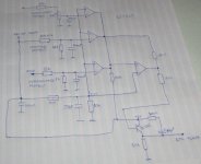
I draw simple protection circuit for my new switcher. I need your opinion if this thing should work.
At right is a comparator used as flip-flop. I never used it that way but I think it shoud work 😉.
Overcurrent sensing is made with current transformer, diode bridge and capacitor that are not drawn in shematic.
Electrolit capacitor 47uF is used for soft start, as described in design guide for TL494.
Regards,
Janez
Attachments

You could easily simulate it, with the free LTspice software, from http://www.linear.com . (The software is also known as SwitcherCADIII, but is a great, full-featured circuit simulator.)
Thanks, this simulator is realy good, but somehow I can't get my circuit working. I'm interested only in output comparator used as flip-flop and transistor.
Today I will try my circuit at test board. I'm mostly afraid that during startup some comparator will triger and shut down SMPS. I haven't been working a lot with comparators in practice, so I'm not sure what happens when power is applied.
In my workshop is freezing, as I don't have heating there, othervise I would test it already 😀. Also instruments don't work corectly
Regards,
Janez
The output comparator is not a latch. Instead it is a comparator with positive feedback and thus hysteresis. When the fault condition is removed, the comparator will switch back to the no fault state. You are also right that the circuit may not work correctly on start up. Finally, how fast do you want the circuit to be. The caps seem large.
yor circuitry will not work for sure.
1. 339 is open collector so you need pull-up resistor for each output.
2. because of same reason as in previous, you will need diode for each output to separate outputs one from another.You will need to connect diode after pull-up resistor
3. And i asume that it is much better to use logic 'And' circuit with 3 inputs instead of last comparator, because it will be much faster and you will not need to think about feedback for each comparator.
Gain of comparator with open loop is very bad choice for pwm, as you intend to use. You need to use any compensation techniques for closed loop fedback stability but it is not necessary.
Sorry, i have not noticed where you drew junctions, so you don't need scheme that i drew.
But for overcurrent protection you must use any kind of stability control, or your flip-flop will always be 'On' when you start your circuit under load, or you will need to tune treshold current much more than you should expect, or to use bigger caps at input, but this will slowdown protection.
But for overcurrent protection you must use any kind of stability control, or your flip-flop will always be 'On' when you start your circuit under load, or you will need to tune treshold current much more than you should expect, or to use bigger caps at input, but this will slowdown protection.
Belive or not, circuit works great 😀
I had some problems when power was applied, but I solved it by adding 47nF capacitor between outputs of comparators and +5V, so when power is applied, + input of output comparator is much higher than reference voltage and it doesn't trigger.
Outputs of comparators are active low, so when they are triggered, they are connected to ground. So when any of them is triggered, all outputs drop to zero. Pull-up resistor is 10k. and it serves also for flip-flop as voltage divider with resistor 3k3.
Let me explain how flip flop works. When comparator is not triggered than voltage on + input is 5V and on - input is always 2.5V. When one of input comparators gets triggered, voltage on + input drops to 0V, that triggers comparator and sets output to 0. If fault condition disappears, + input remains lower than reference voltage, because resistors 10k and 3k3 act like voltage divider with voltage of 1,3V.
Capacitors at input of every comparator are 100nF, i think they are not too big, as voltage diferences are quite low. If you have any idea how to improve my circuit (different elements, etc) please tell me, I would be very grateful.
I have no idea how fast protection circuit reacts, but it sure prevents input transistors of SMPS from blowing up. I know because I tried wery hard to destroy them by shorting output, but I didn't succed 😀. I didn't test overheat and overvoltage protection, but I'm sure they work.
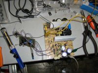
I made short video and few pictures, I will post them, as soon as I compress them.
OK, protection circuit works great, but I have another problem - soft start. I have 10.000uF capacitance at output and SMPS should be able to turn on light bulbs, motors etc. I just can't make smps to turn-on slowly, lets say 2 or 3 seconds until full output voltage. I used even 220uF capacitor at DTC, but it seems there is no effect at all. OK I know that without capacitor transistors just blow (That was my discovery after 2 blown transistors several years ago 😀). What should i do?
Thanks for your help,
Janez
I had some problems when power was applied, but I solved it by adding 47nF capacitor between outputs of comparators and +5V, so when power is applied, + input of output comparator is much higher than reference voltage and it doesn't trigger.
Outputs of comparators are active low, so when they are triggered, they are connected to ground. So when any of them is triggered, all outputs drop to zero. Pull-up resistor is 10k. and it serves also for flip-flop as voltage divider with resistor 3k3.
Let me explain how flip flop works. When comparator is not triggered than voltage on + input is 5V and on - input is always 2.5V. When one of input comparators gets triggered, voltage on + input drops to 0V, that triggers comparator and sets output to 0. If fault condition disappears, + input remains lower than reference voltage, because resistors 10k and 3k3 act like voltage divider with voltage of 1,3V.
Capacitors at input of every comparator are 100nF, i think they are not too big, as voltage diferences are quite low. If you have any idea how to improve my circuit (different elements, etc) please tell me, I would be very grateful.
I have no idea how fast protection circuit reacts, but it sure prevents input transistors of SMPS from blowing up. I know because I tried wery hard to destroy them by shorting output, but I didn't succed 😀. I didn't test overheat and overvoltage protection, but I'm sure they work.
I made short video and few pictures, I will post them, as soon as I compress them.
OK, protection circuit works great, but I have another problem - soft start. I have 10.000uF capacitance at output and SMPS should be able to turn on light bulbs, motors etc. I just can't make smps to turn-on slowly, lets say 2 or 3 seconds until full output voltage. I used even 220uF capacitor at DTC, but it seems there is no effect at all. OK I know that without capacitor transistors just blow (That was my discovery after 2 blown transistors several years ago 😀). What should i do?
Thanks for your help,
Janez
djolejr: Sorry I didn't see your last message. I had a phone call during I was writing. You are right about triggering protection during start-up, I have already asked for help with this problem in my last message. I think (very) slow start would solve this.
I am not sure if this is what you need. But here is what I did, to slow the turn-on speed:
I have an SMPS that is powered from a transformer output plus bridge rectifier and smoothing capacitance (like unregulated linear supply).
I made the SMPS voltage come up more-slowly by inserting a big MOSFET in parallel with a small resistance, between the rectifier bridge and the smoothing caps. The mosfet is turned on after a delay. So the parallel resistance carries almost all of the initial current. By varying the parallel resistance, and the turn-on time of the mosfet, I can set the speed of the power-up. After start-up, the resistor is basically out of the circuit, since the mosfet's Rdson is so small.
I have built quite a few of these power supplies and they seem to work well.
I also use this "soft start" circuit for a regulated linear supply that has 3x 4700 uF smoothing caps and a "large" (47uF) bypass cap on an LD1084 adjustable 3-terminal regulator's adjust pin, in order to prevent the regulator's input voltage from rising so fast, compared to its output voltage, that the maximum in-out differential voltage rating is exceeded.
(Edit: You can actually use either PMOS or NMOS, for the mosfet, with proper configuration, as noted farther below.) For a positive DC voltage system (25VAC-->30VDC), I used a P-channel mosfet, STP80PF55 (like IRF4905, but cheaper; you could use others, instead, if needed), with a 1-Ohm 5W resistor in parallel (i.e. from S to D). I placed a 33K 1/4W resistor from mosfet gate to ground, and 22uF cap in parallel with a 15v Zener from the mosfet's gate to source (zener's cathode and cap's + to mosfet source). Mosfet source was connected to bridge rectifier's + output, and drain was connected to + of smoothing caps.
I also have a very similar version for a negative power rail, which uses an nmosfet. And at the site below, I show a slightly different version, which uses N-channel mosfets for both the positive and negative rails (with STP80NF55-06 n-mosfets).
See the schematics at
http://www.fullnet.com/~tomg/gooteesp.htm ,
which has a couple of linear regulated power supply schematics that include soft-start circuits that are similar to what I described above.
You can also download the LTspice circuits, there, so you can simulate them, and can copy and paste parts of them into other circuits, etc.
The easiest way to set the turn-on speed/characteristics is probably by playing with the values in the simulator (i.e. the 1 Ohm, 33k, and 22uF), after the soft-start portion is pasted into something similar to your circuit. The resistor parallel to the mosfet sets the initial turn-on slope, depending on the caps that follow, and the voltage. And the 33k and 22uF control the speed of the change of the mosfet's Vgs (and it turns on when its threshold is reached).
My values, with my circuit, give about 0.5 second turn-on time, although the actual added delay is less than 0.15 second (since that's all I needed). But the delay can easily be increased.
Note that the 1 Ohm resistors that I use (parallel to mosfet) are only 5-Watt components. That 5W is exceeded, by a very large margin (800W), for a very short time. But it's OK, in my case. Note that some resistor datasheets actually specify those types of allowable short-time overloads. If not, I guess you could "try it and see". But with your longer start-up time, you might have to worry a little more about it.
In my case, the mosfet only dissipates about 0.74 watt, and barely needs a heatsink.
Thaks, it's a nice idea, I'm going to try it, but last night I was thinking about using second error amplifier in TL494 for slow start with capacitor and resistor.
Before I try this, I will connect potentiometer to DTC and try to find out what happens if I change voltage to this pin.
Before I try this, I will connect potentiometer to DTC and try to find out what happens if I change voltage to this pin.
Attachments
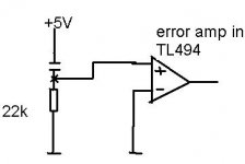
voltage betwen 0V-3.5V (0%-9x%<100%) at DTC or pin 4. directly control pulse widith, and outputs of 2 error amplifiers are connected to DTC so they just amplifier difference betwen + and - and change voltage at DTC. I have tried to use similar overcurrent protection with current transformer in PC PSU ( as car battery charger), it had worked very fine when i tried to shortcircuit it (for several hundreds times), but when i have tried to charge big battery (1,2V) with about 10 Amps (10Amps was overcurrent protection) overcurrent protection did not work as i planed, and simply it was dead.Than i tried to create some kind of current regulation and to use second error amplifier from TL494, and i could not make it to work. I connected Voltage from current transformer to noninvert. (after rectification and after filter ) input and to inv. input i connected Vref (Vref is changeable by pot). But it did not work good.For example i load it with light bulb, and i tried to control current. so i start from 0A and slowly rise it up until light bulb had full brightnes(potentiometer was at middle and Vref=2.5V), but when i tried to reduce current i needed to rotate potentiometer to much (pot was at quarter, Vref=1.2V).
i limit current for some load, but when i connect smaller load ( but big enough to draw more current that i limit) it did not limit current, load consumption of current was more that i limited.
i limit current for some load, but when i connect smaller load ( but big enough to draw more current that i limit) it did not limit current, load consumption of current was more that i limited.
djolejr; I've just take a look at block diagram of TL494 and you are absolutely right about DTC and error amplifier. I don't know, maybe i made a mistake on protoboard and 220uF was not connected correctly.
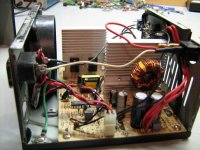
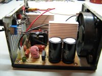
I have similar power supply like you made, but is capable of 25A at 14,4V. When you take a look at primary transistors and transformer you won't belive me 😉. I'm using it almost every day for several years now and I didn't change anything yet, it's pretty undestroyable 😀. It's quite amazing that while I was developing it, I didn't destroy any transistor. With prototype I'm developing now I blew about 6 pairs of transistors, mostly because of stupid mistakes like overheating (I had a phone call during testing 😀), bad isulator, screw under board etc. Diode bridge and fuse survived all of those mistakes.
With switch I select between 12V and 14.4V output. It's able to start with load of 4 bulbs 12V 45W in paralel, but if I connect a bulb while it's working it turns of.
Attachments
Hi,
Why not use a photo-thyristor? It latches and provides isolation between primary and secondary side of your PSU.
Serge
Why not use a photo-thyristor? It latches and provides isolation between primary and secondary side of your PSU.
Serge
Janez said:Thaks, it's a nice idea, I'm going to try it, but last night I was thinking about using second error amplifier in TL494 for slow start with capacitor and resistor.
Before I try this, I will connect potentiometer to DTC and try to find out what happens if I change voltage to this pin.
there is a better way to do slow start, goto http://onsemi.com and search for the tl494 datasheet. Open it up and on page 9 figure 16 you'll find a softstart circuit using the dtc pin.
- Status
- Not open for further replies.
- Home
- Amplifiers
- Power Supplies
- Overcurrent, overheat and overvoltage protection for TL494