Output transformers are an essential part of most tube amplifiers, but they are also a major source of problems.
One of the main sources of these problems is the iron: it is lossy and non-linear.
Completely dispensing with it would therefore be nice, but is it possible?
If you keep the same copper and just remove the iron, the answer is clearly no: the magnetizing inductance would be reduced by a factor of 1,000 or more, making it completely useless for audio purposes.
Without resorting to superconductors, is it possible to find a workaround?
Fortunately, yes: the universe we live in is not simply and linearly scalable, which has interesting implications.
For example, an elephant is not built like an ant, and an ant is capable of incredible feats relative to its size.
For magnetics too, this leads to major differences when the absolute size is modified: a tiny lilliput transformer won't have the same properties as a big one, even if you try to adapt parameters, like the number of turns.
As a rule, magnetic systems tend to be more efficient when absolute size is increased.
This explains why it is possible for the earth to have a magnetic field generated by the "dynamo effect", in spite of its low rotation rate and the (relatively) low conductivity of its liquid core.
This means that if an air-core transformer is made large enough, it will have properties of frequency response and efficiency suitable for audio applications.
A figure of merit of a transformer is the L/R time-constant of its magnetizing inductance.
I just measured an ordinary OPT for example, and its DC resistance is 275Ω, and its inductance 16H, leading to an L/R ratio of 56ms.
Let us compare this to a large air-core transformer: a coil of 1 meter outer diameter having windings of 10x20cm.
Coil Inductance Calculator
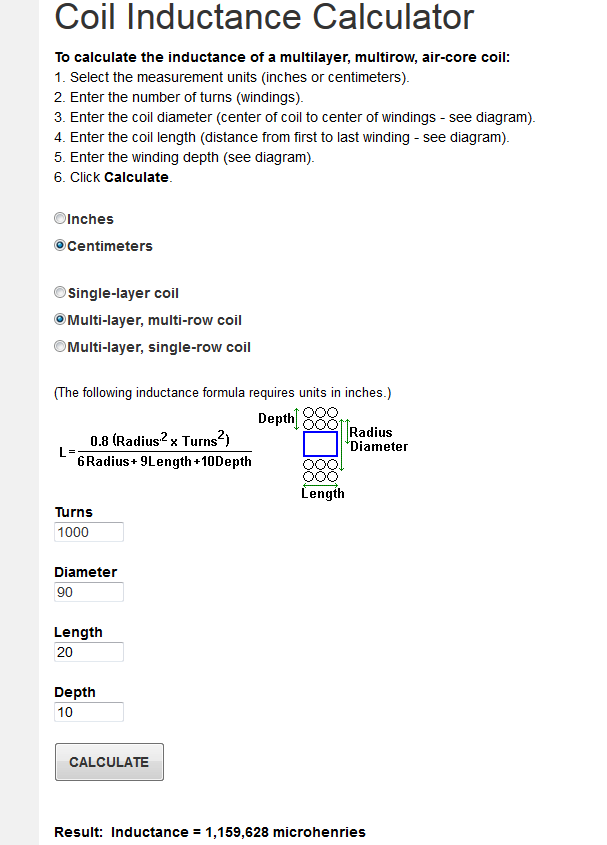
The inductance is 1.16H for 1,000 turn.
As the total copper area is 200cm², the raw section of one turn is 200/1000=0.2cm²=20mm².
If the packing factor is 0.5 and the area allocated to the secondary is the same as for the primary, this results in an effective copper area of 5mm²/turn.
As the total wire length is ~=2830m, the total winding resistance is 9.51Ω
Wire DC resistance calculator
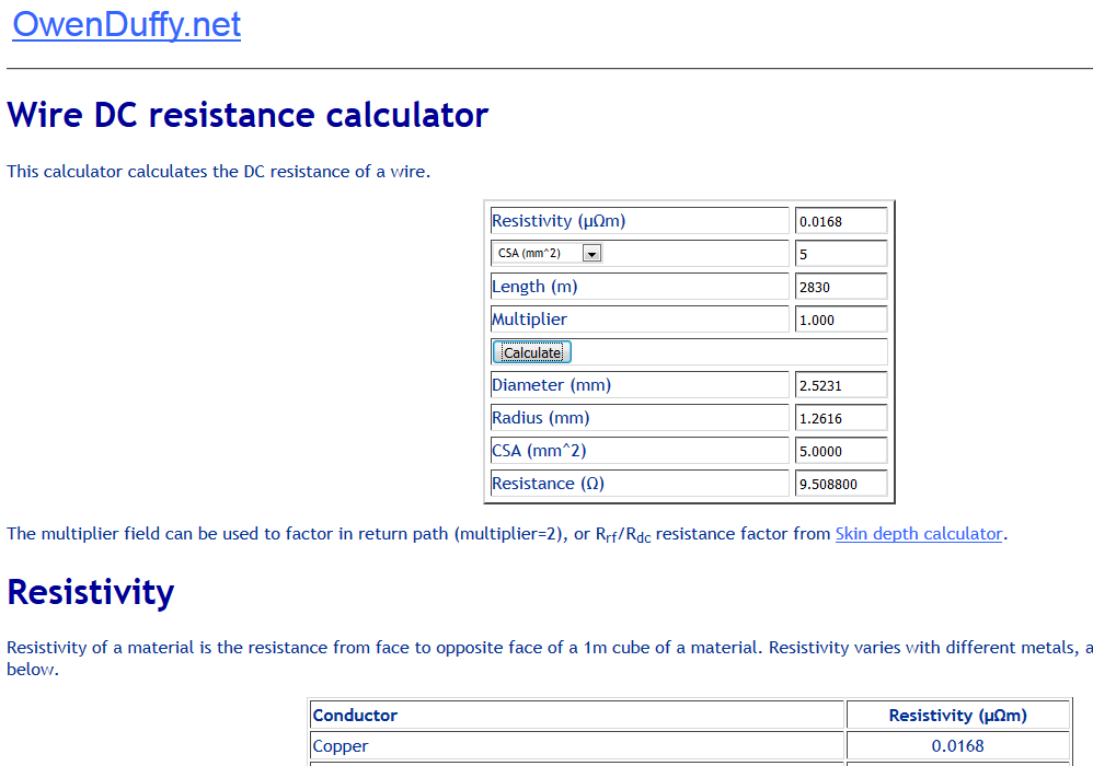
The time constant is therefore 1.16/9.51=122ms, which compares favorably to the ordinary iron transformer.
What about the leakage inductance?
With a winding of such a size, it will be very easy to intertwine the primary and secondary very tightly, and the insulation thickness relative to the conductor size will be small, leading to a low leakage inductance.
What about the footprint, the weight, the magnetic field generated?
Size or cost are no obstacle to the true audiophile, and immersing simultaneously in the magnetic and acoustic fields of music is certainly the ultimate listening experience.
In addition, the OPT could double as a transducer if a large membrane and magnetic bias system is added....
One of the main sources of these problems is the iron: it is lossy and non-linear.
Completely dispensing with it would therefore be nice, but is it possible?
If you keep the same copper and just remove the iron, the answer is clearly no: the magnetizing inductance would be reduced by a factor of 1,000 or more, making it completely useless for audio purposes.
Without resorting to superconductors, is it possible to find a workaround?
Fortunately, yes: the universe we live in is not simply and linearly scalable, which has interesting implications.
For example, an elephant is not built like an ant, and an ant is capable of incredible feats relative to its size.
For magnetics too, this leads to major differences when the absolute size is modified: a tiny lilliput transformer won't have the same properties as a big one, even if you try to adapt parameters, like the number of turns.
As a rule, magnetic systems tend to be more efficient when absolute size is increased.
This explains why it is possible for the earth to have a magnetic field generated by the "dynamo effect", in spite of its low rotation rate and the (relatively) low conductivity of its liquid core.
This means that if an air-core transformer is made large enough, it will have properties of frequency response and efficiency suitable for audio applications.
A figure of merit of a transformer is the L/R time-constant of its magnetizing inductance.
I just measured an ordinary OPT for example, and its DC resistance is 275Ω, and its inductance 16H, leading to an L/R ratio of 56ms.
Let us compare this to a large air-core transformer: a coil of 1 meter outer diameter having windings of 10x20cm.
Coil Inductance Calculator
The inductance is 1.16H for 1,000 turn.
As the total copper area is 200cm², the raw section of one turn is 200/1000=0.2cm²=20mm².
If the packing factor is 0.5 and the area allocated to the secondary is the same as for the primary, this results in an effective copper area of 5mm²/turn.
As the total wire length is ~=2830m, the total winding resistance is 9.51Ω
Wire DC resistance calculator
The time constant is therefore 1.16/9.51=122ms, which compares favorably to the ordinary iron transformer.
What about the leakage inductance?
With a winding of such a size, it will be very easy to intertwine the primary and secondary very tightly, and the insulation thickness relative to the conductor size will be small, leading to a low leakage inductance.
What about the footprint, the weight, the magnetic field generated?
Size or cost are no obstacle to the true audiophile, and immersing simultaneously in the magnetic and acoustic fields of music is certainly the ultimate listening experience.
In addition, the OPT could double as a transducer if a large membrane and magnetic bias system is added....
Attachments


I must admit I have always wondered what kind of dimensions an air-core output transformer would take on. If anything it would be a fascinating experiment if not a bit crazy!
16 Henry at 275 Ohm must be a SE OT, because that would be very poor for a P-P OT.
So you are really talking air core versus air core here apparently.
For a P-P OT equivalence you'll need a 50x bigger air core OT to equal the L primary. (2500 x area)
Electromagnetics, Laplace, Coulomb... are extremely linear. Only steel magnetization versus current is non-linear.
So you are really talking air core versus air core here apparently.
For a P-P OT equivalence you'll need a 50x bigger air core OT to equal the L primary. (2500 x area)
Electromagnetics, Laplace, Coulomb... are extremely linear. Only steel magnetization versus current is non-linear.
Last edited:
16 Henry at 275 Ohm must be a SE OT, because that would be very poor for a P-P OT.
And of course inductance should be compared to load and source impedances. 1.16H is no good for 99.99% of tube amplifiers.
For 16H over 2300 turns would be needed if the ratio the other parameters were the same. So DC resistance would be higher or an even bigger transformer would be needed....
Moreover 16H would only be ok for 2.5K (or lower primary impendance) transformer.
Last edited:
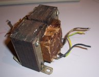
It is a PP transformer, pulled from a wrecked Seeburg or Wurlitzer a long time ago:16 Henry at 275 Ohm must be a SE OT, because that would be very poor for a P-P OT.
16H is measured at a test-instrument level: quite low, not sufficient to overcome the hysteresis, and at 1kHz. The large signal value is larger:
Connected to 230V 50Hz, it draws 4.5mA, which translates to ~162H.
But the 16H value has relevance, because in an amplifier the load transition from small signal to large signal sweeps the whole range, and causes distortion.
This shows what hysteresis and eddy currents caused by poor quality iron can do.
A lower, but constant value is preferable from that point of view.
You missed the point: what counts is the L/R constant, not the absolute value related to a specific turn number.And of course inductance should be compared to load and source impedances. 1.16H is no good for 99.99% of tube amplifiers.
I could (and perhaps should) have normalized everything to a single turn, but values of µΩ and nH aren't as telling, which is why I chose an arbitrary 1,000 turn number.
You are free to choose any number of turns to suit impedances, the L/R value will remain identical if the total quantity of copper remains the same*
Of course, the L/R constant of 120ms is still small, and would be better suited to a SE amp, but:
a) It is completely linear
b) You can freely add even more copper for a larger L/R:
I chose 1m outer diameter because it is a nice round number, but the dimensions can be increased arbitrarily, and the form factor can also be optimized, I just decided on those dimensions to show that it is a workable solution if you are really ready to spend some bucks in a hundred pounds of copper or so.
The rest is simply an engineering problem: after all, the most powerful electromagnets presently in existence are still resistive, copper based....
*If the inductance is scaled to the 275Ω of the example transformer, it becomes 0.12*275=33H -not large, but more acceptable-
Attachments
Last edited:
Would it be better as a toroid? (do air core toroid inductors even have an electromagnetic advantage over solenoid core?)

You missed the point: what counts is the L/R constant, not the absolute value related to a specific turn number.
You miss the most important point: It is the combination of source and load impedances that matters. If not enough you only get a lot of distortion regardless of high or low Rdc. Even Rdc=0 using hypothetical superconductive wire would not be a guarantee for anything.....
Last edited:
jcx -- but is there any advantage in terms of L/Rs? I know if an iron core is used, it saturates way faster than an H core. Because of no gaps, I assume. Of course with air core it's ALL gap!
Transformer distortion
In the design of a good audio transformer, winding capacitances and leakage inductance have to be kept as low as possible. Accordingly, number of turns has to be as low as possible. This can only be achieved by using a high permeability core. To get reasonable inductance without core, leakage inductance and winding capacitance will be so large that the transformer will be hardly usable.
But is OPT distortion such a big problem?
Distortion due to core saturation is not really a problem. Just use large enough core.
The real problem is hysteresis distortion, which does not depend on the signal level.
DC coercive force (A/m) of different magnetic materials:
Non-oriented silicon steel: 400-600
Permalloy (40-50% Ni): 100-200
Grain-oriented silicon steel: 80-100
Mu metal (80% Ni): 20-40
Metglass (amorphous iron): 20-40
Vitroperm (nanocrystalline iron): 3
Annealed round supermalloy (80% Ni): 2
Vitroperm and supermalloy have such low hysteresis that its contribution to transformer distortion is virtually nonexistent. This is why these materials are used for highest quality audio transformers. Unfortunately, they have low saturation flux and are expensive, so their use for conventional OPT is out of the question. They can be used in dedicated output transformers for higher frequencies of the audio spectrum, where small core can handle a lot of power without saturation.
Comparison between non-oriented and grain-oriented steel shows that GOS has 5-6 times lower hysteresis distortion. To realize this advantage, the core has to be a toroid or a C-core.
Amorphous is in turn better than GOS, and amorphous cores are available large enough and reasonably priced for an OPT with a very low hysteresis distortion.
NiFe soft alloys with Ni=48%-50% are much better than that.
The 4750, high perm 49, permenorm 5000 H2 and others (different names and slightly different specs depending on the manufacturer) have coercive force around 5-7 A/m only.
They also have relatively high saturation flux at 1.5-1.6T and high initial permeability around 4000-5000 at just B=20 Gauss (max 50000) in the form of typical transformer laminations.
Much better than nano-crystalline and amorphous garbage.. 😀 .. that also have serious manufacturing issues.
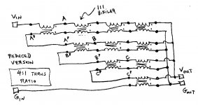
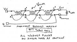
Avoid induction altogether with a transmission line xfmr:
(tongue in cheek, still requires a magnetic core for end to end isolation)
Just a bunch of transmission lines with one end of them connected up in series, and the other ends connected up in parallel to provide impedance transformation. Cores are placed over the lines to provide Voltage isolation between the ends, the more the better (defines the primary inductance seen). Optimization proceeds from left to right in the diagrams. 4 to 1 turns ratio gives 16 to 1 impedance ratio. The final version does not have leakage inductance, but rather a characteristic impedance (like a transmission line). Low end of bandwidth is determined by the primary inductance seen.
Attachments


Last edited:
Yes, the number of different materials with different names from different manufacturers is mind-boggling, and data that the manufacturers provide are obtained using different measurement conditions. Often different sources give different values for the apparently same material, and some characteristics of high grade materials, such as coercive force and initial permeability, are extremely sensitive to minor changes in processing conditions, and very difficult to reproduce batch to batch.
The point was that transformer distortion is relatively minor, and even the cheap M6 material is pretty good, if used in tape-wound cores. Coreless OPT does not seem to be workable.
The point was that transformer distortion is relatively minor, and even the cheap M6 material is pretty good, if used in tape-wound cores. Coreless OPT does not seem to be workable.
Vitroperm and supermalloy have such low hysteresis that its contribution to transformer distortion is virtually nonexistent. This is why these materials are used for highest quality audio transformers. Unfortunately, they have low saturation flux and are expensive, so their use for conventional OPT is out of the question. They can be used in dedicated output transformers for higher frequencies of the audio spectrum, where small core can handle a lot of power without saturation.
Nanocrystalline is slightly more expensive than amorphous (c-cores); it does not make a transformer much more expensive than an amorphous one as the major cost factor in winding is labour.
With proper Afe, nanocrystalline is very well usable for OPT's as well; I use nanocrystalline c-cores for IT's and OPT's, even for full range high impedance applications like 211 tubes. But yes they grow big 😀
Last edited by a moderator:
Not all nanocrystallines are the same. I referred to one specific variety, Vitroperm 500F made by Vacuumschmelze GMBH. The stuff is absolutely gorgeous, it is like the best supermalloy, but almost two times the saturation flux density. With one of the cores, only 50 turns will give you 1 H (on a double core). For $50 plus shipping from Mouser, it is possible to wind an outstanding interstage transformer. But bigger cores suitable for a small OPT are out of my price range.
nanocrystalline core Vacuumschmelze Ferrite Toroids / Ferrite Rings | Mouser
nanocrystalline core Vacuumschmelze Ferrite Toroids / Ferrite Rings | Mouser
Last edited:
As interesting a concept as this is, is a core really so bad? You might get more distortion at lower frequencies - but then again you still would with a perfect core and limited inductance, the valve still has to drive a diminishing impedance with frequency to make the magnetic field in the first place. At least a core gives you more headroom to work with - even if you might abruptly hit an inductance brick wall with saturation at low frequencies - but this rarely if ever happens with a normal music signal.
Exactly.
Everyone worries about some tiny amount of hysteresis current, but the Gorilla farting in the room is just plain old magnetizing current. (90 deg out of phase, it turns the load line into an ellipse) The transformer couples the voltages without voltage distortion*. It just adds magnetizing current. You always want the -maximum- primary inductance you can get to minimize that. Not some constant low inductance.
Put some local N Fdbk around the output tubes to lower their Zout then**, to handle any residual magnetizing current, and you are flying high, even with an Edcor OT.
*(small exception at high freq. due to leakage L dropping the Vout, but that's easily fixed with N Fdbk)
** (one could also put some small inductance in the cathode circuit, using the same type of magnetic material as the OT, to cause automatic compensation for residual OT magnetizing current)
Last edited:
In a sense I would also agree, particularly regarding what is audible and what not.
It is not that difficult to make an OPT with distortion <1%. (It existed since the days of the Williamson.) That brings its contribution in line with that of the power stage (P.P.). The complete Mullard 5-20 amplifier has maximum distortion of 0,05%.
It is not that difficult to make an OPT with distortion <1%. (It existed since the days of the Williamson.) That brings its contribution in line with that of the power stage (P.P.). The complete Mullard 5-20 amplifier has maximum distortion of 0,05%.
- Status
- Not open for further replies.
- Home
- Amplifiers
- Tubes / Valves
- Output transformers: let's think big, see big