Hello All,
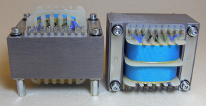
I recently acquired a couple of output transformers from 'an auction site'. They look to be quite well made and the claimed specs seem good, too: low-capacitance windings, 14-layer inter-leaved windings, Kapton insulation, 10-170kHz at 3400/8ohms.
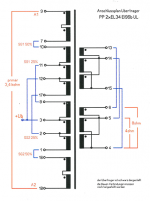
The wiring diagram shows how to wire these for 3400ohm Raa primary with screen grid taps at 25% and 50%. It looks like I could wire it slightly differently to get a ~4250 Raa with a screen grid tap at 40% by connecting 8 to 17 (B+, +Ub on the diagram) and using leads 2 and 11 (alone) for the screen grid taps. I hooked it up like that to test with a small voltage and it gave values as expected.
My question is whether I can safely assume this would work in the final circuit (B+ ~450V, power 30W). The somewhat higher Raa would be preferred in the circuit I am implementing (the Claus Byrith '4-30' amp).
Also, a question regarding wiring the actual leads together. Is it preferred to wire the posts 'directly', that is, a wire from 1 to 16, 8 to 17, etc. as short as possible across the transformer and bring just the minimum number of wires to inside the chassis? Or bring all the leads to within the chassis and connect as appropriate there? Or is it just a style thing?
Thanks for your help!
- Michael (aka hummel)
As an aside, does anyone happen to know who might have made these?
I recently acquired a couple of output transformers from 'an auction site'. They look to be quite well made and the claimed specs seem good, too: low-capacitance windings, 14-layer inter-leaved windings, Kapton insulation, 10-170kHz at 3400/8ohms.
The wiring diagram shows how to wire these for 3400ohm Raa primary with screen grid taps at 25% and 50%. It looks like I could wire it slightly differently to get a ~4250 Raa with a screen grid tap at 40% by connecting 8 to 17 (B+, +Ub on the diagram) and using leads 2 and 11 (alone) for the screen grid taps. I hooked it up like that to test with a small voltage and it gave values as expected.
My question is whether I can safely assume this would work in the final circuit (B+ ~450V, power 30W). The somewhat higher Raa would be preferred in the circuit I am implementing (the Claus Byrith '4-30' amp).
Also, a question regarding wiring the actual leads together. Is it preferred to wire the posts 'directly', that is, a wire from 1 to 16, 8 to 17, etc. as short as possible across the transformer and bring just the minimum number of wires to inside the chassis? Or bring all the leads to within the chassis and connect as appropriate there? Or is it just a style thing?
Thanks for your help!
- Michael (aka hummel)
As an aside, does anyone happen to know who might have made these?
Attachments
Keep the wires short, no idea whether this proposal will work well or not, (did not do the analysis) depends to some extent on how the windings interact when connected differently than originally intended.
Try it and see, measurements should tell the tale. No possibility of getting more information from the seller? Probably your best lead.
Try it and see, measurements should tell the tale. No possibility of getting more information from the seller? Probably your best lead.
- Status
- Not open for further replies.