That OT diagram looks a lot like the setup that Hammond uses (or used to on older OTs). An 8 Ohm winding with a 4 Ohm tap. Connecting the other 4 Ohm winding across the 0 and 4 Ohm tap just increases the current output capability, still 4 Ohm across the 0 to 4 tap and 8 Ohm across the 0 to 8 taps.
You connect the extra 4 Ohm winding in series with the 0 to 4 Ohm taps to get 16 Ohm out from the series combo. Looks like the diagram has the extra winding connected across the wrong taps. (will smoke the OT in that case since the 4 to 8 Ohm taps are actually a 2 Ohm winding, not 4)
You connect the extra 4 Ohm winding in series with the 0 to 4 Ohm taps to get 16 Ohm out from the series combo. Looks like the diagram has the extra winding connected across the wrong taps. (will smoke the OT in that case since the 4 to 8 Ohm taps are actually a 2 Ohm winding, not 4)
Last edited:
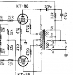
When the secondary are connected in parallel, as in the drawing below, which is the final impedance? I need this information to adjust the feed back loop.
Any help is welcome.
Ok, Thank you ,
but is this true if the windings impedance were with different values? In this case, 4-8 is in parallel with 0-16.😕
"0-16" is actually another 4R winding as smoking-amp said, here is the wiring diagram for the Hammond OPT, which should be similar to the one used in TVA-1.
An externally hosted image should be here but it was not working when we last tested it.
That OT diagram looks a lot like the setup that Hammond uses (or used to on older OTs). ...
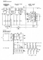
Thank you, but this is Michaelson & Austin power amplifier and the drawing is ok.
Unfortunately, I don't have a unit to do some measurements. It uses half of 8 ohm (winding) to connect in parallel with 0-16 windings.
"0-16" is actually another 4R winding as smoking-amp said, here is the wiring diagram for the Hammond OPT, which should be similar to the one used in TVA-1.
An externally hosted image should be here but it was not working when we last tested it.
Got it. Now makes sense. Thank you.
It's labeled in a misleading way - windings need to the same number of turns to be connected in parallel, or it will be effectively a number of shorted turns.
It's labeled in a misleading way - windings need to the same number of turns to be connected in parallel, or it will be effectively a number of shorted turns.
That's why it makes sense. Two windings of 4r in parallel.
Thank you for confirm that.
Apnneto,
As the Hammond schematics showed and Tom Bavis and Smoking Amp said.
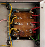
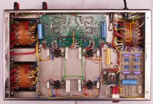
Your photo does not clearly show what is wired how (some detail is hidden behind the right panel.)
To give a simple arithmetic example, referring to the sketch in your first post: Say one assumes 10 windings between the bottom '0' and '4' taps, then there will be a further 4 windings from '4' to '8' ohm, which are 14 windings altogether for that section. The top section will equally have a second 10-turn winding from the '0' to the '16' marked terminal (never mind if it sounds wrong).
That then gives two separate 10 turn windings (4 ohms) in parallel for a 4 ohm output impedance. As said the parallel windings do not change the impedance, much as two 6,3V windings in parallel still give 6.3V, only capable of double current. To get to 16 ohm the two 4 ohm windings go in series, thus twice the windings and four times the impedance. The 8 ohm tap is somewhat of a 'bastard' connection. For 8 ohms one has the two 4 ohm windings (10 turns) in parallel plus an extra 4 windings not used before from the lower secondary. [Ratio 14/10 = 1,4, squared for impedance, which gives 2 x 4 = 8 ohms for the appropriate tap.]
Pardon the grade 1 explanation, but you will notice that real connections cannot be as pictured in your intro schematic; you will have two unequal windings in parallel. The physical connections as per the photo look factory-made, so please check as per the description in case someone made a booboo. (You can also use a separate say 50V mains transformer connected to the OPT primary, and measure secondary output voltages, all sec. sections disconnected, just to make sure.)
As the Hammond schematics showed and Tom Bavis and Smoking Amp said.
Your photo does not clearly show what is wired how (some detail is hidden behind the right panel.)
To give a simple arithmetic example, referring to the sketch in your first post: Say one assumes 10 windings between the bottom '0' and '4' taps, then there will be a further 4 windings from '4' to '8' ohm, which are 14 windings altogether for that section. The top section will equally have a second 10-turn winding from the '0' to the '16' marked terminal (never mind if it sounds wrong).
That then gives two separate 10 turn windings (4 ohms) in parallel for a 4 ohm output impedance. As said the parallel windings do not change the impedance, much as two 6,3V windings in parallel still give 6.3V, only capable of double current. To get to 16 ohm the two 4 ohm windings go in series, thus twice the windings and four times the impedance. The 8 ohm tap is somewhat of a 'bastard' connection. For 8 ohms one has the two 4 ohm windings (10 turns) in parallel plus an extra 4 windings not used before from the lower secondary. [Ratio 14/10 = 1,4, squared for impedance, which gives 2 x 4 = 8 ohms for the appropriate tap.]
Pardon the grade 1 explanation, but you will notice that real connections cannot be as pictured in your intro schematic; you will have two unequal windings in parallel. The physical connections as per the photo look factory-made, so please check as per the description in case someone made a booboo. (You can also use a separate say 50V mains transformer connected to the OPT primary, and measure secondary output voltages, all sec. sections disconnected, just to make sure.)
Hi Johan,
Thank you for your post.
Unfortunately I don't have an original OT for testing and measuring. In fact, I'm cloning the TVA Amplifier. Nevertheless, what I've got till now is the output impedance used to feed the feedback loop. It's for sure 4 ohms, since it used the 4-8 ohms to parallel the 0-16.
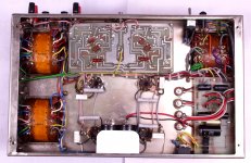
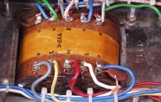
There's a lot of pictures of this amplifier on internet and everything pointed to what the schematics is showing. Look at the new pictures.
Other point is that I've got a good operation point near what is on schematic, so I'm working starting with 4 ohms taps.😉
Thank you for your post.
Unfortunately I don't have an original OT for testing and measuring. In fact, I'm cloning the TVA Amplifier. Nevertheless, what I've got till now is the output impedance used to feed the feedback loop. It's for sure 4 ohms, since it used the 4-8 ohms to parallel the 0-16.
There's a lot of pictures of this amplifier on internet and everything pointed to what the schematics is showing. Look at the new pictures.
Other point is that I've got a good operation point near what is on schematic, so I'm working starting with 4 ohms taps.😉
Attachments
Nice job!I hope you get many joyful hours listening to it,I think I've got more confidence now to proceed with the one here .good luck on future projects and thank you .biffo.
Keep in mind that Parallel winding produces cross-currents, unless they are bi-filar wound...
In small transformers you can get away with it...But large transformer in the MW range it is asking for major trouble....
In small transformers you can get away with it...But large transformer in the MW range it is asking for major trouble....
Nice job!I hope you get many joyful hours listening to it,I think I've got more confidence now to proceed with the one here .good luck on future projects and thank you .biffo.
Hi biffo,
Thanks. After two years, I finally started enjoy this amplifier.

My final step is to adjust the amount of GNFB. I'm very close to what I was expecting ... Very nice sound with strong and controlled bass.🙂
Keep in mind that Parallel winding produces cross-currents, unless they are bi-filar wound...
In small transformers you can get away with it...But large transformer in the MW range it is asking for major trouble....
Thanks for your advice.
Considering that I'm using a big OT already tested for 100w/35 hz, this will not be a problem, since it has normal taps: 0,4,8 and 16 ohms. If I were designing a new OT, this would be a problem ... I know nothing about projecting a transformer.

An externally hosted image should be here but it was not working when we last tested it.
Sorry Folks,
You are mistaken.
The two output transformer secondaries are not shorted together in this amplifier.
The two secondaries (output: 0-4-8) and the feedback secondary (0 - 16) are only connected at the + speaker output, thereby giving twice output voltage in reverse phase for error correction.
What this does is provide an 180° out-of-phase feedback signal to the input and phase-splitter stage for error-correction.
Beautiful circuit. i use this topologe due to ti's beauty.
Last edited:
hope you noticed this thread has been dead for 5 years.
I guess some missed the funeral.... 🙄
- Home
- Amplifiers
- Tubes / Valves
- Output Transformer Windings in parallel