That's just a sample layout that's also a proven commercial success and has a cult following....
That is a nice amplifier, but you do need Ultra Linear taps on the output transformer.
...
Actually, I'd strongly advise against a 1:1 carbon copy of this circuitry. I own an ST-60 and I don't like the sound one bit, because of the thick velvet draperies it puts over my beloved Quad ESL57. It was then on long term loan to a friend, who hated the sound so much he somehow managed to kill it. The major organs are still intact, so I'm in the process of redesigning it.
There's some truth around the global feedback taboo, even though the Bode/Black thingy is by no mean a black art. The thing is, Leak, and many others, wanted so much to publish sexy numbers they just botched it: the open loop bandwidth of the ST-60 is only 3KHz! Yes, that's into sand/chip territory.
Am not terribly experienced with custom layouts, but what others have said here indicates that you are likely okay with your original plan--having the OPT very close together.
I've found that agonizing over this level of placement choice is less important than the way things are eventually wired up. That power switch is potentially an issue--on my first amp, I had a power switch on the front. The AC wiring went right behind the choke. Turned out that I could hear nasty hash from my LED dimmer lights when turned on. Moving the power switch (and associated wiring) helped with that. It's probably possible to wire it up without issue, but moving that may un-cramp the top plate a bit?
Personally, I like that capacitor between the PT and the choke. The current loop between the rectifier, choke, and C1/2 looks to me like it would be minimal there compared to putting it next to the OPTs.
I've solicited plenty of layout and build advice online and, like I said, it's really hard for anyone to say what's going to happen or best. You really just have to do it!
Thanks for the advice Thekak (and all)! You're right re: agonizing... I'll try to come up with a responsible way to rough it in prior to chassis fabrication, and will move the power switch to the back near the IEC and fuse.
On all amp building keep your inputs and input cable runs away from mains transformers. That's the hole I fell into. So don't put you RCA inputs under the mains transformers. I created a magnetic loop with slightly different cable runs on inputs and that coupled in hum. Fun to find. RCA inputs insulated from chassis are good so the coax ground goes to the input valve near the cathodes. Use the same valve for L and R inputs for the same reason.
I think I would place the input valves on the bottom left on your layout #15 and EL34's the in the bottom middle. It may help with heater routing and keeping heater currents away from the input stages. The RCA's would be under the OPT's if you want them on the back.
You need to power the 12AY7 heater off DC to eliminate the last of the buzz or reduce the input log volume to 22k.
Last edited:
Merlinb,
I am sorry, I did not make it clear which amplifier.
I replied to Zung's Post # 11.
Schematic: Leak Stereo 60 (Ultra Linear Amplifier).
Anything else is not a Leak Stereo 60.
I am sorry, I did not make it clear which amplifier.
I replied to Zung's Post # 11.
Schematic: Leak Stereo 60 (Ultra Linear Amplifier).
Anything else is not a Leak Stereo 60.
Thanks for the suggestions and to your points....
Thanks!
I've rearranged a few things to keep the mains as short as possible and as far away from the signal path as possible. As you suggest, RCA inputs will be insulated from the chassis, but a bit unclear as to where the coax ground should end up. I was going to attach the shield at the input as I've had good luck attaching it at the RCA in the past, but maybe I just got lucky. Where specifically would you suggest tying it in according to the schematic? Or were you suggesting a chassis ground near the input valve?On all amp building keep your inputs and input cable runs away from mains transformers. That's the hole I fell into. So don't put you RCA inputs under the mains transformers. I created a magnetic loop with slightly different cable runs on inputs and that coupled in hum. Fun to find. RCA inputs insulated from chassis are good so the coax ground goes to the input valve near the cathodes. Use the same valve for L and R inputs for the same reason.
I'll mess around with the layout a bit and see if I can shift the tubes. Right now I'm pretty happy with the layout as I have a couple of terminal boards that fit nicely between the 12AU/Y7s and the EL34s and the symmetry is pleasing. I'll probably keep the circuit pretty accurate to the original to start and tweak from there. I'm curious though about why powering the 12AY7 off DC or reducing the input log might help with buzz? New to these things and would love to know your thoughts.I think I would place the input valves on the bottom left on your layout #15 and EL34's the in the bottom middle. It may help with heater routing and keeping heater currents away from the input stages. The RCA's would be under the OPT's if you want them on the back.
You need to power the 12AY7 heater off DC to eliminate the last of the buzz or reduce the input log volume to 22k.
Thanks!
It's always difficult to know what makes a real difference and what does not. Screen of the RCA to the volume control, screen of the volume control to the first stage junction of the 100uF cathode resistors. The amp is sensitive to the cathode grid voltage difference of the first tube. So returning the input ground there does not add any unwanted hum. Chassis ground well good question. I place a 10R and 47nF between chassis and signal ground some would say adding back-to-back diodes is safer. If the amp is the only unit (ie not the tuner) that's grounded, then you can connect the chassis directly to the signal. Otherwise, you can create a hum loop through your mains sockets.
Another approach is to ground the signal and chassis together but lift the 100uF and 1K5 grounds on the cathode and place a series 10R resistor from the junction of these to signal ground. The input volume control ground then gets returned to the 10R rather than true ground. This acts like a pseudo differential input. Some call it hum buck.
If you join the chassis to signal my preference is at the power supply just after the main reservoir cap. You must ensure the rectifier return currents go to the main cap first. So the main cap makes a good star earth.
AC heater contains higher harmonics from the HT rectifiers if they share the same mains transformer. These can get from the heater to the grid via stray internal and external capacitance producing a high pass filter and a buzz. 1pF with 100k input is enough. Sometimes it's OK just depends on layout and valve. The lower the input impedance the lower the buzz. So you often get buzz when the volume control is in the middle but non at min or max. You may get benefit from using two 100R resistors on each 6.3V ac leg from the transformer and grounding the center rather than grounding one side.
Getting 6.3V DC from 6.3V AC is a little tricky, you need Schottky diode rectifiers a big cap and a low dropout regulator. I think you can get boards on diyaudio.
The output damping would benefit from a small amount of NFB, you could add this into the cathode of the first stage and use a 12AX7 to increase open loop gain - but it's fine without. Better speaker damping will improve any bass boom.
I've found out most of these things the hard way. But these loads of stuff on hum loops.
Last edited:
An option (with all due essential cautions) is plugging the primary of one OPT into the wall and scoping the other floating OPT.Also, in this position do they seem far enough away from the PT?
In the case of power transformers it was surprising to discover just how much cross talk to can occur to chokes during rectification impulses.
This approach sounds interesting! Might try this if things are noisy.Another approach is to ground the signal and chassis together but lift the 100uF and 1K5 grounds on the cathode and place a series 10R resistor from the junction of these to signal ground. The input volume control ground then gets returned to the 10R rather than true ground. This acts like a pseudo differential input. Some call it hum buck.
And this might be a vote for a stepped attenuator... perhaps in conjunction with the 100R resistors on the 6.3V AC legs from the transformer. Thanks for you input!AC heater contains higher harmonics from the HT rectifiers if they share the same mains transformer. These can get from the heater to the grid via stray internal and external capacitance producing a high pass filter and a buzz. 1pF with 100k input is enough. Sometimes it's OK just depends on layout and valve. The lower the input impedance the lower the buzz. So you often get buzz when the volume control is in the middle but non at min or max. You may get benefit from using two 100R resistors on each 6.3V ac leg from the transformer and grounding the center rather than grounding one side.
Screen of the RCA to the volume control, screen of the volume control to the first stage junction of the 100uF cathode resistors. The amp is sensitive to the cathode grid voltage difference of the first tube. So returning the input ground there does not add any unwanted hum.
Are you saying that the potentiometer ground should connect to the spot I have indicated with a red arrow?
Attachments
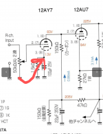
If you were to do that the first tube wouldn't get negative grid voltage resulting in a lot of distortion (when signal comes in) and a low anode voltage. What Thekak means is that you best tie the separate ground points of the first tube together.
Am working on minimizing ground-related 120Hz on an amp in-progress. Found a lot of interesting information in baudouin0's quoted post and was looking for more precise language. My thinking is, as you suggested, the "junction" referred to would need to be after the cathode resistor and bypass capacitor.If you were to do that the first tube wouldn't get negative grid voltage resulting in a lot of distortion (when signal comes in) and a low anode voltage. What Thekak means is that you best tie the separate ground points of the first tube together.
I think the intention was to minimize the signal & ground current loop area from the input to the first stage triodes.
When you wish to minimize loop area of two conductors, twisted pair cabling is one possibility. A narrow coaxial could be another.
But baudouin0 had also many other ideas. Check them too.
When you wish to minimize loop area of two conductors, twisted pair cabling is one possibility. A narrow coaxial could be another.
But baudouin0 had also many other ideas. Check them too.
- Home
- Amplifiers
- Tubes / Valves
- Output Transformer Proximity... Can they be too close together?