OK, so after running this amp for a while I've noticed something new. It works, and sounds great BUT, the right channel output transformer is generating heat while the left channel transformer is cold to the touch. I've run this amp for a few years and the output transformers have always been cold to the touch but this time, the right channel is noticeably warmer than it's ever been. It's not hot, just warm and makes me wonder what the difference is and why its generating heat. I've checked voltages on both channels and they are very close (within 2 - 3 volts) to what my schematic shows, nothing out of the ordinary. I've swapped output tubes, driver tubes, and changed rectifiers. I've swapped speakers too. Just easy things I could do to troubleshoot. Still, the right channel output TX is getting warm while the left channel is cold. To me, this suggests I have more current running through the right channel but again, the voltages are right. Not sure what I might be missing. Any ideas or things I should target?
Attachments
DC voltages indicates that you might not have a DC short. It doesn't mean it doesn't have an AC short circuit. Is the right channel still hotter if the amp just idle with no input signals?
Do you have a current probe to check the DC current draw on each CH ??
If you have a fuse for the H.T. you can put your meter probes across the fuse holder terminals and remove the fuse to measure the DC current..
The last time I had a very similar problem like this...the filter cap in the B+ was leaking DC current to ground.... You can lift the ground leg of the filter caps with a current meter in series ....you can the measure either AC ripple current or DC leakage current and see whats going on...
Dear cerrem: a leakage in an electrolytic or bypass condenser will not cause an output transformer warming.
Dear cerrem: a leakage in an electrolytic or bypass condenser will not cause an output transformer warming.
Your right..sorry I mis-read the post....
I thought he was referring to the Power Transformer..... LOL
Just let the amp sit idle for some time with NO AUDIO signal passing through.....
If your still getting hot with no audio signal, then atleast you narrow this down to DC issues..
Hopefully you do not have very high frequency oscillation ...
Last edited:
Try to measure -with good LCR meter- both OPT's primary DCR and inductance (of course power off, and without output tubes).
If you have shorting within primary windings (adjacent turns, or windings above each other), the DCR and the self inductance will be different.
If you have shorting within primary windings (adjacent turns, or windings above each other), the DCR and the self inductance will be different.
I was thinking if there is a kind of capacitor from plate of the output tube to cathode or ground, perhaps some value between 0.001 and 0.01µF, and it may be leaky causing more DC current flowing in the trafo's primary.
Are you sure that no heating element (for example large wattage resistor) under "hot" OPT?
If one channel current changed (caused some trouble, for example changed operating point), rising anode/cathode current would provoking extra warming.
If one channel current changed (caused some trouble, for example changed operating point), rising anode/cathode current would provoking extra warming.
riverty,
Simple, safe, and effective things to try:
First, power down the amp. Those B+ filter caps will only discharge while the tubes are warm, there will still be some residual voltage, you can get a shock.
Check with your VOM or DMM before wiring, or getting your hands in there.
Get a 50k 10Watt, or two 25k 5 Watt resistors in series and solder them across the second B+ filter cap. Now you have a bleeder resistor that will discharge the rest of the high voltage (usually takes up to 30, 60, or 120 seconds). Check with your meter to see that.
Whenever you have the amp powered up, and the wiring exposed, be careful not to move the amp (usually upside down, make sure it is suspended in a very stable manner), or to let your probes slip as you make live measurements, or your hands may move to a high voltage point. Hands out is the rule.
Now you can proceed with the rest of the tests and questions below:
Swap the output tubes.
Does the “warm” move to the other output transformer?
Does the “warm” stay on the same transformer?
Measure the output tubes cathode voltages (with no signal).
Are those voltages similar?
If one is much higher, there is lots more current, and a hot output transformer (and a hot tube too).
Then remove the bypass caps across those cathode resistors.
Again, with no signal, do one or both the cathode voltages increase (if so, you have found a leaky bypass cap or caps). Leaky bypass caps cause more tube current.
Check the voltage on the output tubes control grids. It should be near 0V. If it is not, you may have a gassy tube. Or, much less likely, the coupling cap is leaky.
If it was running ok and cool before, on a particular set of loudspeakers, I doubt that it suddenly has ultrasonic oscillations (unless caused by the 6SN7 circuit particulars).
But if the negative feedback was nearly unstable, and then you changed loudspeakers, it might have ultrasonic oscillations now.
I would be sure to use a separate 330 Ohm resistor for each 6SN7 grid (4 resistors).
Wire each one right onto the appropriate tube socket tabs (2 each 330 Ohm resistors, 2 tabs, 2 grids, one 6SN7), and repeat for the other channel.
I wanted to post a reply as to not leaving anyone hanging here. I appreciate everyone's help on this.
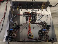
After hacking on this particular build many times over the years testing this, listening to that, trying these caps, etc. The build (everything underneath the chassis) got pretty ugly. I even managed to break off a few tabs on one of my tube sockets and had to replace the socket with a used one I had laying around.
I decided to gut the amp and replace with new parts. Chassis, transformers, controls and outboard connections were all OK, just the tube sockets and passive components were replaced with new.
As you might think, this fixed my leaky capacitor / output transformer heating problem and the amp is back to good - very good indeed.
Thanks again for all your help! Everyone on here rocks!
Regards,
Attachments
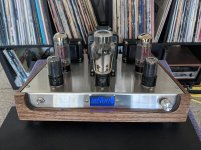
Very nice build! I like how you have everything on the top plata with bent front and rear flanges. Might try that sometime if I could get access to a sheetmetal brake.
What is your input sensitivity and power output on this design? It looks like you are using JJ 6L6GC for out put tube. The schematic shows 6L6GT.
What is your input sensitivity and power output on this design? It looks like you are using JJ 6L6GC for out put tube. The schematic shows 6L6GT.
Last edited:
Francois G, you are right. I am using JJ 6L6GC (I've corrected that on my newer schematic) and not the 6L6GT.
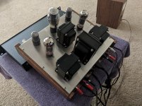
The top chassis "deck" is laser cut from 1/8" brushed stainless steel and yes, two 90 degree bends for the front and rear apron. Everything is mounted on the chassis.
I only have a scope (and my ear) to find distortion figures, so:
Sensitivity is:
2V input @ 1Khz = 7.7V out (7.4 watts) max / 6.1V (4.6 watts before visual clipping on my scope)
1.5V input @ 1Khz = 7.2V out (6.4 watts) max / 6.1V (4.6 watts before visual clipping on my scope)
Generally, a 5-watt stereo, single-ended, UL amp. It does sound great and is very quiet. I would make this amp for anyone who would want one. Unfortunately, they are not cheap but my price would be quite competitive with other makes out there. Message me if interested.
Enjoy...
- Status
- Not open for further replies.
- Home
- Amplifiers
- Tubes / Valves
- Output Transformer Heat?